Download
1 / 34
830 likes | 2.59k Vues
MATERIALS SCIENCE & ENGINEERING . Part of . A Learner’s Guide. AN INTRODUCTORY E-BOOK. Anandh Subramaniam & Kantesh Balani Materials Science and Engineering (MSE) Indian Institute of Technology, Kanpur- 208016 Email: anandh@iitk.ac.in, URL: home.iitk.ac.in/~anandh.

E N D
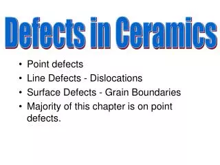
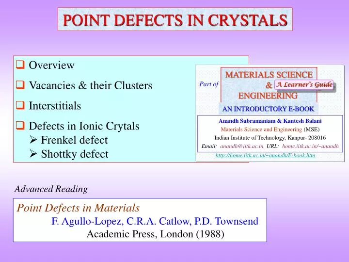
MATERIALS SCIENCE & ENGINEERING Part of A Learner’s Guide AN INTRODUCTORY E-BOOK Anandh Subramaniam & Kantesh Balani Materials Science and Engineering (MSE) Indian Institute of Technology, Kanpur- 208016 Email:anandh@iitk.ac.in, URL:home.iitk.ac.in/~anandh http://home.iitk.ac.in/~anandh/E-book.htm POINT DEFECTS IN CRYSTALS • Overview • Vacancies & their Clusters • Interstitials • Defects in Ionic Crytals Frenkel defect Shottky defect Advanced Reading Point Defects in Materials F. Agullo-Lopez, C.R.A. Catlow, P.D. Townsend Academic Press, London (1988)
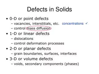
Point defects can be considered as 0D (zero dimensional) defects. • The more appropriate term would be ‘point like’ as the influence of 0D defects spreads into a small region around the defect. • Point defects could be associated with stress fields and charge • Point defects could associate to form larger groups/complexes→ the behaviour of these groups could be very different from an isolated point defect In the case of vacancy clusters in a crystal plane the defect could be visualized as an edge dislocation loop • Point defects could be associated with other defects (like dislocations, grain boundaries etc.) Segregation of Carbon to the dislocation core region gives rise to yield point phenomenon ‘Impurity’/solute atoms may segregate to the grain boundaries • Based on Origin Point defects could be Random (statistically stored) or StructuralMore in the next slide • Based on Position Point defects could be Random (based on position) or OrderedMore in the next slide
Point defects can be classified as below from two points of view • The behaviour of a point defect depends on the class (as below) a point defect belongs to Based on origin Point Defects Statistical Structural Arise due to off-stoichiometry in an compound (e.g. in NiAl with B2 structure Al rich compositions result from vacant Ni sites) Arise in the crystal for thermodynamic reasons Point Defects Based on position Random Ordered Occupy random positions in a crystal Occupy a specific sublattice Vacancy ordered phases in Al-Cu-Ni alloys (V6C5, V8C7)
Point Defects Based on source Intrinsic Extrinsic No additional foreign atom involved Atoms of another species involved Vacancies Self Interstitials Anti-site defects In ordered alloys/compounds Note: Presence of a different isotope may also be considered as a defect
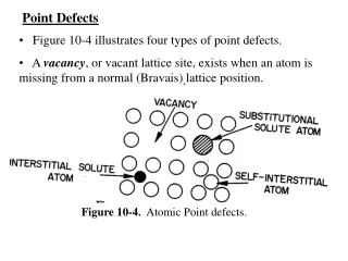
Vacancy Interstitial Non-ioniccrystals Impurity Substitutional 0D(Point defects) Frenkel defect Ioniccrystals Other ~ Schottky defect • Imperfect point-like regions in the crystal about the size of 1-2 atomic diameters • Point defects can be created by ‘removal’, ‘addition’ or displacement of an atomic species (atom, ion) • Defect structures in ionic crystals can be more complex and are not discussed in detail in the elementary introduction
Vacancy • Missing atom from an atomic site • Atoms around the vacancy displaced • Stress field produced in the vicinity of the vacancy • Based on their origin vacancies can be Random/Statistical (thermal vacancies, which are required by thermodynamic equilibrium) or Structural (due to off-stoichiometry in a compound) • Based on their position vacancies can be random or ordered • Vacancies play an important role in diffusion of substitutional atoms • Vacancies also play an important role in some forms of creep • Non-equilibrium concentration of vacancies can be generated by: quenching from a higher temperature or by bombardment with high energy particles
Relativesize Interstitial Compressive & Shear Stress Fields Impurity Or alloying element Substitutional Compressive stress fields Tensile StressFields • SUBSTITUTIONAL IMPURITY/ELEMENT Foreign atom replacing the parent atom in the crystal E.g. Cusitting in the lattice site of FCC-Ni • INTERSTITIAL IMPURITY/ELEMENT Foreign atom sitting in the void of a crystal E.g. C sitting in the octahedral void in HT FCC-Fe
In some situations the same element can occupy both a lattice position and an interstitial position► e.g. B in steel
Interstitial C sitting in the octahedral void in HT FCC-Fe • rOctahedral void / rFCC atom = 0.414 • rFe-FCC = 1.29 Å rOctahedral void = 0.414 x 1.29 = 0.53 Å • rC = 0.71 Å • Compressive strains around the C atom • Solubility limited to 2 wt% (9.3 at%) Interstitial C sitting in the octahedral void in LT BCC-Fe • rTetrahedral void / rBCC atom = 0.29 rC = 0.71 Å • rFe-BCC = 1.258 Å rTetrahedral void = 0.29 x 1.258 = 0.364 Å • ► But C sits in smaller octahedral void- displaces fewer atoms • Severe compressive strains around the C atom • Solubility limited to 0.008 wt% (0.037 at%)
Why are vacancies preferred in a crystal (at T> 0K)? • Formation of a vacancy leads to missing bonds and distortion of the lattice • The potential energy (Enthalpy) of the system increases • Work required for the formation of a point defect → Enthalpy of formation (Hf) [kJ/mol or eV/defect] • Though it costs energy to form a vacancy, its formation leads to increase in configurational entropy (the crystal without vacancies represents just one state, while the crystal with vacancies can exist in many energetically equivalent states, corresponding to various positions of the vacancies in the crystal → ‘the system becomes configurationally rich’) • above zero Kelvin there is an equilibrium concentration/number of vacancies • These type of vacancies are called Thermal Vacancies(and will not leave the crystal on annealing at any temperature → Thermodynamically stable) • Note: up and above the equilibrium concentration of vacancies there might be a additional non-equilibrium concentration of vacancies which are present. This can arise by quenching from a high temperature, irradiation with ions, cold work etc. • When we quench a sample from high temperature part of the higher concentration of vacancies present (at higher temperature there is a higher equilibrium concentration of vacancies present) may be quenched-in at low temperature
Calculation of equilibrium concentration of vacancies • Let n be the number of vacancies, N the number of sites in the lattice • Assume that concentration of vacancies is small i.e. n/N << 1 the interaction between vacancies can be ignored Hformation (n vacancies) = n . Hformation (1 vacancy) • Let Hf be the enthalpy of formation of 1 mole of vacancies S = Sconfigurational G (putting n vacancies) = nHf T Sconfig G = H T S zero For minimum Assuming n << N User R instead of k if Hf is in J/mole
Variation of G with vacancy concentration at a fixed temperature • Close to the melting point in FCC metals Au, Ag, Cu the fraction of vacancies is about 104 (i.e. one in 10,000 lattice sites are vacant)
Even though it costs energy to put vacancies into a crystal (due to ‘broken bonds’), the Gibbs free energy can be lowered by accommodating some vacancies into the crystal due to the configurational entropy benefit that this provides • Hence, certain equilibrium concentration/number of vacancies are preferred at T > 0K
Ionic Crystals • In ionic crystal, during the formation of the defect the overall electrical neutrality has to be maintained (or to be more precise the cost of not maintaining electrical neutrality is high) Frenkel defect • Cation being smaller get displaced to interstitial voids • E.g. AgI, CaF2 • Ag interstitial concentration near melting point: in AgCl of 103in AgBr of 102 • This kind of self interstitial costs high energy in simple metals and is not usually found [Hf(vacancy) ~ 1eV; Hf(interstitial) ~ 3eV]
Schottky defect • Pair of anion and cation vacancies • E.g. Alkali halides Missing Anion Missing Cation
Other defects due to charge balance (/neutrality condition) • If Cd2+ replaces Na+→ one cation vacancy is created Schematic
Defects due to off stiochiometry • ZnO heated in Zn vapour → ZnyO (y >1) • The excess cations occupy interstitial voids • The electrons (2e) released stay associated to the interstitial cation Schematic
Other defect configurations: association of ions with electrons and holes X2 anion associated with a hole M2+ cation associated with an electron
How do colours in some crystals arise due to colour centres? Actually the distribution of the excess electron (density) is more on the +ve metal ions adjacent to the vacant site Colour centres (F Centre) Violet colour of CaF2→ missing F with an electron in lattice Red Visible spectrum: 390-750 nm
Some more complications: an example of defect association Two adjacent F centres giving rise to a M centre
Structural Point defects • In ordered NiAl (with ordered B2 structure) Al rich compositions result from vacancies in Ni sublattice • In Ferrous Oxide (Fe2O) with NaCl structure there is a large concentration of cation vacancies. Some of the Fe is present in the Fe3+ state correspondingly some of the positions in the Fe sublattice is vacant leads to off stoichiometry (FexO where x can be as low as 0.9 leading to considerable concentration of ‘non-equilibrium’ vacancies) • In NaCl with small amount of Ca2+ impurity: for each impurity ion there is a vacancy in the Na+ sublattice Antisite on Al sublattice ← Ni rich side Al rich side → vacancies in Ni sublattice NiAl Antisite on Al sublattice ← Fe rich side Al rich side → antisite in Fe sublattice FeAl The choice of antisite or vacancy is system specific
FeO heated in oxygen atmosphere → FexO (x <1) • Vacant cation sites are present • Charge is compensated by conversion of ferrous to ferric ion: Fe2+ → Fe3+ + e • For every vacancy (of Fe cation) two ferrous ions are converted to ferric ions → provides the 2 electrons required by excess oxygen
Point Defect ordering • Using the example of vacancies we illustrate the concept of defect ordering • As shown before, based on position vacancies can be random or ordered • Ordered vacancies (like other ordered defects) play a different role in the behaviour of the material as compared to random vacancies
Schematic Origin of A sublattice Origin of B sublattice Crystal with vacancies As the vacancies are in the B sublattice these vacancies lead to off stoichiometry and hence are structural vacancies Vacancy ordering Examples of Vacancy Ordered Phases: V6C5, V8C7
Vacancy Ordered Phases (VOP) • Me6C5 trigonal ordered structures (e.g. V6C5 → ordered trigonal structure exists between ~1400-1520K)(The disordered structure is of NaCl type (FCC lattice) with C in non-metallic sites) Space group: P31 The disordered FCC basis vectors are related to the ordered structure by:
Association of Point defects (especially vacancies) • Point defects can occur in isolation or could get associated with each other (we have already seen some examples of these). • If the system is in equilibrium then the enthalpic and entropic effects (i.e. on G) have to be considered in understanding the association of vacancies. • If two vacancies get associated with each other (forming a di-vacancy) then this can be visualized as a reduction in the number of bonds broken, leading to an energy benefit (in Au this binding energy is ~ 0.3 eV). but this reduces the number of configurations possible with only dissociated vacancies. The ratio of vacancies to divacancies decreases with increasing temperature. • Similarly an interstitial atom and a vacancy can come together to reduce the energy of the crystal would preferred to be associated. • Non-equilibrium concentration of interstitials and vacancies can condense into larger clusters. In some cases these can be visualized as prismatic dislocation loop or stacking fault tetrahedron). • Point defects can also be associated with other defects like dislocations, grain boundaries etc. • We had considered a divacancy. Similar considerations come into play for tri-vacancy formation etc. Click here to know more about Association of Defects Concept of Defect in a Defect & Hierarchy of Defects Click here to know more about Defect in a Defect
Complex Point Defect Structures: an example • The defect structures especially ionic solids can be much more complicated than the simple picture presented before. Using an example such a possibility is shown. • In transition metal oxides the composition is variable • In NiO and CoO fractional deviations from stoichiometry (103 - 102)→ accommodated by introduction of cation vacancies • In FeO larger deviations from stoichiometry is observed • At T > 570C the stable composition is Fe(1x)O [x (0.05, 0.16)] • Such a deviation can ‘in principle’ be accommodated by Fe2+ vacancies or O2 interstitials • In reality the situation is more complicated and the iron deficient structure is the 4:1 cluster → 4 Fe2+ vacancies as a tetrahedron + Fe3+ interstitial at centre of the tetrahedron + additional neighbouring Fe3+ interstitials • These 4:1 clusters can further associate to form 6:2 and 13:4 aggregates Note: these are structural vacancies Continued…
Schematic 4:1 cluster → 4 Fe2+ vacancies as a tetrahedron + Fe3+ interstitial at centre of the tetrahedron + additional neighbouring Fe3+ interstitials The figure shows an ideal starting configuration- the actual structure will be distorted with respect to this depiction
Methods of producing point defects • Growth and synthesisImpurities may be added to the material during synthesis • Thermal & thermochemical treatments and other stimuli Heating to high temperature and quench Heating in reactive atmosphere Heating in vacuum e.g. in oxides it may lead to loss of oxygen Etc. • Plastic Deformation • Ion implantation and irradiation Electron irradiation (typically >1MeV)→ Direct momentum transfer or during relaxation of electronic excitations) Ion beam implantation (As, B etc.) Neutron irradiation
What is the equilibrium concentration of vacancies at 800K in Cu Solved Example Data for Cu: • Melting point = 1083 C = 1356K • Hf (Cu vacancy) = 120 103 J/mole • k (Boltzmann constant) = 1.38 1023 J/K • R (Gas constant) = 8.314 J/mole/K First point we note is that we are below the melting point of Cu 800K ~ 0.59 Tm(Cu) If we increase the temperature to 1350K (near MP of copper) Experimental value: 1.0 104
If a copper rod is heated from 0K to 1250K increases in length by ~2%. What fraction of this increase in length is due to the formation of vacancies? Solved Example Data for Cu: • Hf (Cu vacancy) = 120 103 J/mole • R (Gas constant) = 8.314 J/mole/K Cu is FCC (n = 4) Continued…