Download
1 / 55
610 likes | 663 Vues
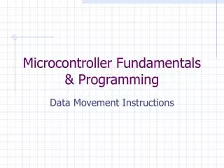
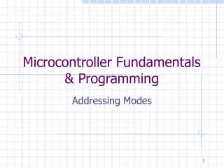
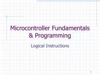
Microcontroller Fundamentals. B. Furman 03FEB2015. Learning Objectives. Explain the general architecture of a microcontroller List the key features of the ATmega328 microcontroller Explain the features and elements of the Arduino and Spartronics Experimenter Shield (SES)

E N D
Microcontroller Fundamentals B. Furman 03FEB2015
Learning Objectives • Explain the general architecture of a microcontroller • List the key features of the ATmega328 microcontroller • Explain the features and elements of the Arduino and Spartronics Experimenter Shield (SES) • Explain the concepts of microcontroller pins as inputs and outputs • Convert between binary and hexadecimal digits
PowerSource SignalConditioning PowerInterface UserInterface Actuator Sensor System toControl ME 110 ME 136 ME 154 ME 157 ME 182 ME 189 ME 195 Mechatronics Concept Map ME 106 ME 120 Controller(Hardware & Software) ME 106 ME 190 ME 187 ME 106 INTEGRATION ME 106 ME 120 ME 106 ME 154 ME 157 ME 195 ME 120 ME 297A BJ Furman 22JAN11
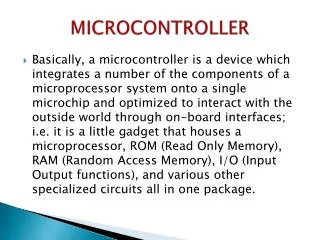
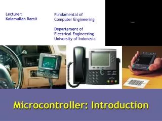
What is a Microcontroller? ANALOGINPUTS What is the difference between a ‘Digital Input’ and an ‘Analog Input’? http://www.freescale.com/files/microcontrollers/doc/ref_manual/M68HC05TB.pdf
ATmega328 Internal Architecture ATmega328 data sheet pp. 2, 5 http://www.adafruit.com/index.php?main_page=popup_image&pID=50
ATmega328 Features ATmega328 data sheet p. 1 http://www.atmel.com/Images/Atmel-8271-8-bit-AVR-Microcontroller-ATmega48A-48PA-88A-88PA-168A-168PA-328-328P_datasheet.pdf
Arduino Duemilanove http://www.arduino.cc/en/Main/ArduinoBoardDuemilanove See the handout: Arduino_ATmega328_pin_mapping_and_schematic Pin 13 LED Digital pins header USBconnector Reset button ATmega328 MCU Barrel jack Analog pins header Power-ground header http://arduino.cc/en/uploads/Main/ArduinoDuemilanove.jpg
Arduino Uno R3 ATmega16u2 replaces FT232RL for USB-serial communication http://www.adafruit.com/index.php?main_page=popup_image&pID=50 See: http://learn.adafruit.com/arduino-tips-tricks-and-techniques/arduino-uno-faq
Arduino Due Note: 3.3 V !! Atmel SAM3X8E processor (32 bit ARM Cortex M3 architecture, 84MHz) http://www.adafruit.com/index.php?main_page=popup_image&pID=1076 See: http://arduino.cc/en/Main/ArduinoBoardDue
Arduino Duemilanove/Uno Features http://www.arduino.cc/en/Main/ArduinoBoardDuemilanove
http://arduino.cc/en/uploads/Main/arduino-duemilanove-schematic.pdfhttp://arduino.cc/en/uploads/Main/arduino-duemilanove-schematic.pdf
ATmega328 Microcontroller Pin number Pin name Special function Note the limitations! p. 316 Source:http://www.atmel.com/dyn/products/product_card.asp?PN=ATmega328P
Absolute Maximums ATmega328 data sheet p. 316
Microcontroller Ports and Pins • The communication channels through which information flows into or out of the microcontroller • Ex. PORTB • Pins PB0 – PB7 • May not be contiguous • Often bi-directional C See next slides!
Port Pin Data Directionality • Input • When you want to take information from the external world (sensors) into the MCU • Output • When you want to change the state of something outside the MCU (turn a motor on or off, etc.) • Pins default to input direction on power-up or reset • Your program can set or change the directionality of a pin at any time
ATmega328Block Diagram Input Output
Setting the Pin Data Direction • Arduino • pinMode(pin_no., dir) • Ex. Make Arduino pin 3 (PD3) an output • pinMode(3, OUTPUT); • pinMode(PIN_D3, OUTPUT); // with me106.h • Note: one pin at a time • Suppose you wanted Arduino pins 3, 5, and 7 (PD3, PD5, and PD7) to be outputs? • Is there a way to make them all outputs at the same time? • Yes! Answer coming later…
Pin Voltages • Microcontrollers are fundamentally digital devices. For digital IO pins: • Information is ‘coded’ in two discrete states: • HIGH or LOW (logic: 1 or 0) • Voltages • TTL • 5 V (for HIGH) • 0 V (for LOW) • 3.3 V CMOS • 3.3 V (for HIGH) • 0 V (for LOW)
Pin Used as an Output • Turn on an LED, which is connected to pin Arduino pin 0 (PD0) (note the resistor!) • What should the data direction be for pin 0 (PD0)? • pinMode(____, ____); • Turn on the LED • digitalWrite(0,HIGH); • Turn off the LED • digitalWrite(0,LOW); ATmega328 Arduinopin 0(PD0)
Pins as Inputs and Pull-up Resistors - 1 • Using a switch as a sensor • Ex. Seat belt sensor • Detect the switch state • What should the data direction be for Arduino pin 3 (PD3)? • pinMode(____, ____); • What will the voltage be on PD3 when the switch is closed? • What will the voltage be on PD3 when the switch is open? • Indeterminate! ATmega328 Arduinopin 3(PD3)
Pins as Inputs and Pull-up Resistors - 2 • Switch as a sensor, cont. • Make the voltage on the pin determinate by turning on the pull-up resistor for PD3 • Assuming PD3 is an input: • digitalWrite(3,HIGH); turns on the “pull-up” resistor • pinMode(3,INPUT_PULLUP); • What will the voltage on PD3 be when the switch is open? • VTG • What will the voltage on PD3 be when the switch is closed? ATmega328 VTG= +5V 1 PD3 0
Pins as Inputs and Pull-up Resistors - 3 • Switch as a sensor, cont. • To turn off the pull-up resistor • Assuming PD3 is an input: • digitalWrite(3,LOW); turns the “pull-up” resistor off ATmega328 VTG= +5V 1 PD3 0
Pins as Inputs and Pull-up Resistors - 4 • Possibility of ‘weak drive’ • Pin set as an input with a pull-up resistor turned on can source a small current • Remember this! ATmega328 VTG= +5V iweak 1 PD3 0
Spartronics Experimenter Shield RC servo header Digital pins header RGB LED Red-RGB jumper Tact switches Red LEDs Piezospeaker Pwr-gnd header Reset button Photoresistor Temperature sensor Potentiometer Analog pins header
Handling the Arduino - How NOT to Do It! Improper Handling - NEVER!!!
Handling the Arduino - The Proper Way Proper Handling - by the edges!!!
Spartronics Experimenter LED Pinout • Pin and LED map • 11 - LED0 (red) • 9 - LED1 (red) or RGB (green) • 6 - LED2 (red) or RGB (blue) • 3 - LED3 (red) or RGB (red) • 13 - LED on Arduino Jumper determines whether pins map to red LEDs or the RGB 11 9 6 3
Spartronics Experimenter Digital Pin Assignments See the Introduction to the Arduino Microcontroller laboratory exercise
Spartronics Experimenter Analog Pin Assignments See the Introduction to the Arduino Microcontroller laboratory exercise
Binary and Hexadecimal Numbers - 1 • Microcontrollers are fundamentally digital (as opposed to ‘analog’) and use binary logic • Two states: high and low, 1 or 0, on or off • Often 5V or 0V • One binary digit is called a bit • It can take on two possible states: 1 or 0 • Eight binary digits are called a byte • Four binary digits are called a nibble
Binary and Hexadecimal Numbers - 2 • Byte and bits Bit No. Upper nibble(4 bits) Lower nibble(4 bits) LSB(Least Significant Bit) MSB(Most Significant Bit)
Binary and Hexadecimal Numbers - 3 Place Value (Base 10 or decimal number) (Base 10) Bit No. (Base 2 or binary number ) (Base 10) • What range of decimal values can 4 bits represent? • How many values in total can 4 bits represent? 0 to 15 16
Binary and Hexadecimal Numbers - 4 HEX Binary Why is hex important? One hex digit can be used as shorthand to represent four binary digits Two hex digits can be used as shorthand to represent eight binary digits or one byte
Practice • 0b11000111 in hex (0b is C notation that says, “interpret what follows as a binary number”) • 0b10011001 in hex • 0b10011001 as a base 10 number • 0x5A in binary (use 8 bits) • 0b11111111 in hex and as a base 10 number • (37)10 in binary and hex the prefix '0x' is C notation that means that the digits which follow are hex digits the prefix '0b' means that the digits which follow are binary digits Back to PORT details
Solution • 1100 0111 in hex = 0xC7 • 1001 1001 in hex = 0x99 • 1001 1001 in base 10 = 153 • 0x5A in binary = 0b0101 1010 • 0b1111 1111 = 0xFF or 255 • (37) = 0b0010 0101 or 0x25
So What? • Recall the question: • Is there a way change the data direction for a set of pins all at the same time? • All the work of MCU happens through registers (special memory locations) • Registers on the Atmega328 are 8-bits wide • The data direction register (DDRx) handles the data directions for pins in PORTx Source:http://www.atmel.com/dyn/products/product_card.asp?PN=ATmega328P p. 93
Data Direction Register • If the bit is zero -> pin will be an input • Making a bit to be zero == ‘clearing the bit’ • If the bit is one -> pin will be an output • Making a bit to be one == ‘setting the bit’ • To change the data direction for a set of pins belonging to PORTx at the same time: • Determine which bits need to be set and cleared in DDRx • Store the binary number or its equivalent (in an alternate base, such as hex) into DDRx
ATmega328 Registers of Interest • See the ATmega328 data sheet, pp. 76-94 • For digital IO, the important registers are: • DDRx • Data Direction bit in DDRx register (read/write) • PORTx • PORTx PORTx data register (read/write) • PINx • PINx PINx register (read only)
PORT Pin and register details ATmega328 datasheet, pp. 76-94 Jump to bits
Example 1 • Make Arduino pins 3, 5, and 7 (PD3, PD5, and PD7) to be outputs • Arduino approach • Alternate approach pinMode(3, OUTPUT); pinMode(5, OUTPUT); pinMode(7, OUTPUT); DDRD = 0b10101000; or DDRD = 0xA8; or Or if me106.h is used: pinMode(PIN_D3, OUTPUT); pinMode(PIN_D5, OUTPUT); pinMode(PIN_D7, OUTPUT); DDRD | = 1<<PD7 | 1<<PD5 | 1<<PD3; More on this next lecture!
Example 2 • Make pins Arduino pins 0 and 1 (PD0 and PD1) inputs, and turn on pull-up resistors • Arduino approach • Alternate approach pinMode(0, INPUT); pinMode(1, INPUT); digitalWrite(0, HIGH); digitalWrite(1, HIGH); DDRD = 0; // all PORTD pins inputs PORTD = 0b00000011; or PORTD = 0x03; or better yet: Or if me106.h is used: DDRD & = ~(1<<PD1 | 1<<PD0); PORTD | = (1<<PD1 | 1<<PD0); pinMode(PIN_D0, INPUT); pinMode(PIN_D1, INPUT); digitalWrite(PIN_D0, HIGH); digitalWrite(PIN_D1, HIGH); More on this next lecture!
Structure of an Arduino Program /* Blink - turns on an LED for DELAY_ON msec, then off for DELAY_OFF msec, and repeats BJ Furman rev. 1.1 Last rev: 22JAN2011 */ #define LED_PIN 13 // LED on digital pin 13 #define DELAY_ON 1000 #define DELAY_OFF 1000 void setup() { // initialize the digital pin as an output: pinMode(LED_PIN, OUTPUT); } // loop() method runs forever, // as long as the Arduino has power void loop() { digitalWrite(LED_PIN, HIGH); // set the LED on delay(DELAY_ON); // wait for DELAY_ON msec digitalWrite(LED_PIN, LOW); // set the LED off delay(DELAY_OFF); // wait for DELAY_OFF msec } • An arduino program == ‘sketch’ • Must have: • setup() • loop() • setup() • configures pin modes and registers • loop() • runs the main body of the program forever • like while(1) {…} • Where is main() ? • Arduino simplifies things • Does things for you
Digital IO – Practice 1 • ‘Reading a pin’ • Write some lines of C code for the Arduino to determine a course of action if the seat belt has been latched (switch closed). • If latched, the ignition should be enabled through a call to a function ig_enable(). • If not latched, the ignition should be disabled through a call to a function ig_disable() • Write pseudocode first ATmega328 PD3
Digital IO – Practice 1 Solution • ‘Reading a pin’ • Pseudocode: Set up PD3 as an input Turn on PD3 pull-up resistor Read voltage on Arduino pin 3 (PIN_D3) IF PIN_D3 voltage is LOW (latched), THEN call function ig_enable() ELSE call function ig_disable() ATmega328 VTG= +5V 1 PD3 0
Digital IO – Practice 1 Solution • ‘Reading a pin’ • Pseudocode: Set up PD3 as an input Turn on PD3 pull-up resistor Read voltage on Arduino pin 3 (PIN_D3) IF PIN_D3 voltage is LOW (latched), THEN call function ig_enable() ELSE call function ig_disable() ATmega328 VTG= +5V 1 PD3 0 One way (snippet, not full program) #define PIN_SWITCH 3 #define LATCHED LOW pinMode(PIN_SWITCH,INPUT_PULLUP); belt_state = digitalRead(PIN_SWITCH); if (belt_state == LATCHED) { ig_enable(); } else { ig_disabled(); }
Digital IO – Practice 2 ATmega328 • ‘Reading from and writing to a pin’ • Write some lines of C code for the Arduino to turn on a lamp (PD2) and buzzer (PD3) if the key is in the ignition (PD0 closed), but seat belt is not latched (PD1 open) • (diagram shows only one of the two switches, but both are similar) • Pseudocode first PD3 PD2 PD0, PD1
Digital IO – Practice 2 Pseudocode ATmega328 • Pseudocode: Set up data direction of pins Make PD0 and PD1 inputs Turn on pull up resistors for PD0 and PD1 Make PD2 and PD3 outputs Loop forever IF key is in ignition THEN IF belt is latched, THEN Turn off buzzer Turn off lamp ELSE Turn on lamp Turn on buzzer ELSE Turn off buzzer Turn off lamp PD3 PD2 VTG= +5V 1 PD0, PD1 0
Digital IO – Practice 2 (Arduino style code) #define PIN_IGNITION 0 #define PIN_SEATBELT 1 #define PIN_LED 2 #define PIN_BUZZER 3 #define SEATBELT_LATCHED LOW #define KEY_IN_IGNITION LOW #define LED_ON HIGH #define LED_OFF LOW #define BUZZER_ON HIGH #define BUZZER_OFF LOW void setup() { pinMode(PIN_IGNITION, INPUT_PULLUP); // key switch pinMode(PIN_SEATBELT, INPUT_PULLUP); // belt latch switch pinMode(PIN_LED, OUTPUT); // lamp pinMode(PIN_BUZZER, OUTPUT); // buzzer } void loop() { /* see next page for code */} ATmega328 PD3 PD2 VTG= +5V 1 PD0, PD1 0