Download
1 / 30
300 likes | 528 Vues
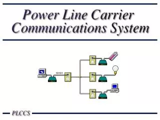
Power Line Telecommunications (PLT). M. Ohishi (NAOJ). http://en.wikipedia.org/wiki/Pandora. Several Names. Power Line Telecommunications (PLT) Power Line Communications (PLC) Broadband over Power Lines (BPL). PLT systems.

E N D
Power Line Telecommunications (PLT) M. Ohishi (NAOJ) http://en.wikipedia.org/wiki/Pandora
Several Names Power Line Telecommunications (PLT) Power Line Communications (PLC) Broadband over Power Lines (BPL) IUCAF Summer School in Tokyo
PLT systems Make use of radio frequency signals applied on the power lines used for the distribution of mains electricity. Because electrical power lines are not designed for the transmission of high data rate signals, PLT signals on electrical power lines have the potential of causing interference to radiocommunication services. IUCAF Summer School in Tokyo
RR 15.12 “Administrations shall take all practicable and necessary steps to ensure that the operation of electrical apparatus or installations of any kind, including power and telecommunication distribution networks, but excluding equipment used for industrial, scientific and medical applications, does not cause harmful interference to a radiocommunication service and, in particular, to a radionavigation or any other safety service operating in accordance with the provisions of these Regulations1.” 115.12.1 and 15.13.1 In this matter, administrations should be guided by the latest relevant ITU-R Recommendations IUCAF Summer School in Tokyo
Wavelength 10m 1m 10cm Active Sun 107 Galaxy Centerbackground 106 Jupiter Quiet Sun 105 Moon Cassiopeia A 104 Radio flux density [Jy] JSR 103 F10.7 M31 102 Jovian synchrotron radiation (top) and solar f10.7 (bottom) 10 Jupiter Rec. ITU-R RA.769 1 10,000 10 100 1,000 Frequency [MHz] (Modified from Kraus, 1986) (1Jy=10-26W/m2/Hz) Objects and Intensities ↑Solar Radio Burst Spectrum (http://sunbase.nict.go.jp) ↑Galactic Noise Level (Hiyama, 2004) ↓Jovian Radio Burst(Konno et al. 2002) ↓Jovian Synchrotron Radiation Protection Criteria for RAS Cassiopeia-A Radio Map (Oya& Iizama, 2003)
the RA bands IUCAF Summer School in Tokyo
Regulations to PLT • US • 1.705-80 MHz • Limits to E-field30mV/m @ 30m (< 30 MHz) • Excluded bands • Exclusion zones47 km from a RA obs. • Germany • Based on ECC Rec (05)04 • Limits to E-field40-8.8 log(f) mV/m @ 3m (1-30 MHz)27 mV/m @ 3m (30 - 1000 MHz) IUCAF Summer School in Tokyo
Regulation for Japanese Broadband PLT since October 2007 No measure to protect the RAS ! • Fundamental idea:No interference to the HF radio services by restricting the leaked electric field at a distance of 10 m not to exceed the ambient noise level • Targeted ambient noise level values:28dBmV/m (2-15MHz), 18dBmV/m (15-30MHz) too high !! • Regulate the common mode current (CM) from a PLT modem • Limits to the CM, ICM, from a PLT modem20dBmA (2-15MHz), 10dBmA (15-30MHz) RMS 9kHz • When connected to a specific ISN(Impedance Stabilized Network)LCL=16dB, DMZ=100W, CMZ=25W (LCL: values measured at outlets) IUCAF Summer School in Tokyo
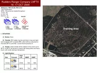
PLT modems & Location PLT Modems:HD-PLC & UPA, one pair each Location: Iitate Observatory, Tohoku U. (Iitate, Fukushima) House:3.6m x 5.4m Measurement Directions: W, S, SE @ 5/10/30m No residences within 1.5km Very low man-made noise IUCAF Summer School in Tokyo
Man-made Noise Rec ITU-R P.372 Four categories: City / Residential / Rural / Quiet Rural Cosmic (Galactic) noise B= 9 kHz IUCAF Summer School in Tokyo
Leakage Measurements • Loop Antenna • ETS-Lindgren 6512(passive loop f 60cm) • Height: 1m(lower edge) • Convert H to E • Spectrum Analyzer • NEC SpeCAT2 • 2-26 MHz • RBW=8kHz • RMS, MAXHOLD • Current Probes • Fair-Rite #43 2643102005 • Primary: 1 turn (CMI) 2 turn (DMI) • Secondary: 7 turns • I [dBmA]=P[dBm]+84 for DMI • I [dBmA]=P[dBm]+90 for CMI IUCAF Summer School in Tokyo
Photos (1) IUCAF Summer School in Tokyo
Photos (2) IUCAF Summer School in Tokyo
Recoding the SW Broadcasting SW Radio: SONY ICF-SW07 IC Recorder: SANYO ICR-PS285RM PLT modem: Panasonic BL-PA510 (HD-PLC, OFDM) SW broadcast at 15370 kHz (China Radio International) was clearly audible. The PLT disturbance masked the CRI at d=5&10m, but at 30m the PLT noise did not mask so much. IUCAF Summer School in Tokyo
Time 2:55.5 2:56.0 2:56.5 2:57.0 2:57.5 2:58.0 2:58.5 2:59.0 2:59.5 3:00.0 Hz 5k 5k 3k 3k 2k 2k 1.5k 1.5k 1k 1k 800 800 600 600 400 400 200 200 IUCAF Summer School in Tokyo
West 5m 10m HD-PLC LIMITS Ambient @ 10m 30m IUCAF Summer School in Tokyo
:Antenna used Antenna Symbol ex)ER:Antenna/Pol. RAS antenna location House Origin(ground) B A I C D E Relative coordinate wrt Origin X:E-W (+:E) Y:: N-S (+:N) Z:: Height 5.9m 7.8m Z-coord. Of antenna:Upper edge of tower IUCAF Summer School in Tokyo
IR:2009/10/19 • Average spectrum (10sec) / RBW=10kHz HD-PLC on RAS Distance = 32 m IUCAF Summer School in Tokyo
BL:2009/10/19 • Average spectrum (10sec) / RBW=10kHz HD-PLC on RAS Distance = 45.5 m IUCAF Summer School in Tokyo
RAS wide band spectra 32m 62m 45.5m 94.5m Average spectra for about 1 min. during HD-PLC on (red) and off (blue) RBW=10kHz (IR & BL) or 30kHz (DL or ER), Detector mode : sample IUCAF Summer School in Tokyo
RAS spectra around a astronomical band (25.61±0.06MHz) 45.5m 94.5m On: -87.4±1.9dB / Off: -93.8±1.5dB (25.61±0.06MHz) On: -97.5±0.6dB / Off: -98.6±0.6dB (25.61±0.06MHz) 126.5m 62m On: -94.7±0.8dB / Off: -97.5±0.6dB (25.55 – 25.62MHz) On: -97.7±0.6dB / Off: -90.0±0.7dB (24.67-24.74MHz) Average spectra for about 1 min. during HD-PLC on (red) and off (blue) RBW=10kHz , Detector mode : sample
Protection Criteria vs Leakage • System Noise=BG (Gal.) noise+ Rx noise (NF=1.5 dB)=15,000 + 120 =15,120 K • Criteria for 2000 sec integ. time = 97.6 mK IUCAF Summer School in Tokyo
How can we avoid disturbance from PLTs? Subtract the PLT disturbance by signal processing • NO! – PLT noise is polarized, thus the digitalsignalprocessing technology in the RAS can not subtractthe PLT noise Separation Distance • ~ 33 km of separation distance is needed for a pair of PLT modems(for free-space propagation) IUCAF Summer School in Tokyo
DMI/CMI at PLT output port HD-PLC UPA PLT modem injects DMIof ~55 dBmA at maximum to power line CMI exceeds the limit in a part of the 2-30 MHz range, however, the limits are valid only when a PLT modem is connected to the ISN. Therefore it is quite natural that the CMI exceeds the limits when The PLT modems are connected to actual power lines. IUCAF Summer School in Tokyo
Common Mode Current (CMI) Distribution Exceeds the CMI limit at around ~3MHz (by ~20dB) Larger than at modem output Very large variation: Max - Min ~ 60dB Standing wave / mechanism to generate CMI
Radiation Mechanism IUCAF Summer School in Tokyo
Measurements in Canada(from Rep. ITU-R SM.2158) IUCAF Summer School in Tokyo
Other Std. Bodies • ITU-T • Rec G.9960for in-house wired network up to 200 (300 ?) MHz • Max power: -55 dBm/Hz • No consultation with ITU-R complains from ITU-R ! • CISPR • Subcomm I • Studies for 10 years with no consensus • Limits by common mode current should not be applied to PLT IUCAF Summer School in Tokyo
Summary Very strong interference caused by the PLT systems was actually measured at 5/10/30 m from the house, which was also detected by the RAS antennas at a distance of up to 130m. Received interference was found to be between 4.5 x 10(4) and 5.2 x 10(5) times the RAS protection criteria. The radiation mechanism is qualitatively and partially qualitatively understood. The data and the radiation mechanism have already been adopted in Report ITU-R SM.2158. IUCAF Summer School in Tokyo
YouTube Video Clip http://www.youtube.com/watch?v=z3yVu5IfaEY50 -300 MHz PLT modem (Belkin) in the UKFM radio is disturbed Many others are found from the above link IUCAF Summer School in Tokyo