Download
1 / 59
780 likes | 1.41k Vues
Fracture mechanics, Mohr circles, and the Coulomb criterion (Stress and failure). Introduction to Fracture Mechanics. In this lecture, we will be focusing on faults: How they form Definitions Stress states Fault strain How we can use faults to tell us things about the geologic history

E N D
Fracture mechanics, Mohr circles, and the Coulomb criterion(Stress and failure)
Introduction to Fracture Mechanics • In this lecture, we will be focusing on faults: • How they form • Definitions • Stress states • Fault strain • How we can use faults to tell us things about the geologic history • Representative structures on planetary bodies
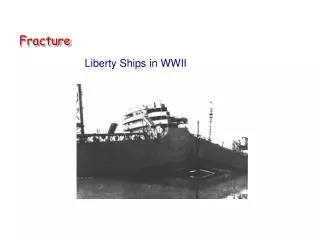
Definitions • Fracture: a pair of distinct surfaces that are separated in a material; ‘‘a structure defined by two surfaces or a zone across which displacement occurs • A joint is a fracture that exhibits only opening displacement (Mode I) • A fault is a planar zone along which shear displacement occurs (Mode II)
Fracture modes • Mode I: opening displacement (joints) • Mode II: in-plane shear (faults) • Mode III: out-of-plane shear (scissors, tearing)
Stress • Stress is force/area, units of pressure (most often bars or pascals) • σ = F/A • Normal stress (σ) acts perpendicular to a surface • Shear stress (τ) acts parallel to a surface
Stress • The “on-in” convention says that the stress component σij acts normal to the ‘i’ direction and parallel to the ‘j’ direction: • Normal stresses i = j • Shear stresses i ≠ j
Stress • Principle stresses have magnitudes and directions • σ1: maximum compressive stress • σ2: intermediate compressive stress • σ3: minimum compressive stress • Principle stresses act on planes that do not ‘feel’ shear stress, i.e., they are normal stresses
Stress • Calculate principle stresses from an arbitrary remote stress state with normal stresses σxandσy, parallel to the x and y axis, respectively • And the orientation of the 2 mutually perpendicular principle planes
Stress example • Given values of σx= 1.2 MPa (compression positive), σy= –0.85 MPa, and τxy= 0.45 MPa, find (a) the principal stresses, and (b) predict the orientations of the principal planes on which the principal stresses act. SOLUTION • Substitute the values of normal and shear stress into equation 1 to obtainσmax,min=1.294MPa and –0.944MPa • Now substitute the same initial values of stress into equation 2 to obtain θp=11.6°and 101.6° • Add 90º to get second plane orientation
Resolving stresses onto planes • To resolve the stresses on a plane is to calculate the magnitude and direction of the normal and shear stresses onto a plane of particular orientation (here, a fault plane) due to the principle stresses
Example • σ1 = 5 MPa, σ2 = 1 MPa, α = 30¡ (to the plane), and θ = 60º (to the plane’s normal). • What is the magnitude of the normal and shear stresses? • σn= 2 MPa (compressive) and τ = 1.7 MPa • Which way is the fault going to slip? • Left-lateral
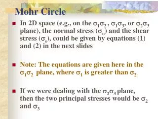
Mohr Circles • Mean stress: describes the confining stress experienced by rock at some depth • (σ1 + σ3)/2 • Differential stress: describes the greatest amount of stress change that a rock can withstand without breaking • (σ1– σ3) • Mohr circles is a geometric representation of these equations used to determine when rock will fracture or when faults will slip
Mohr circles • X and Y axes are normal and shear stress, respectively. • This method only works for compressional normal stress (i.e., compression vs. tension; faults) • Plot σ1 and σ3 on the X axis as points. The difference between these values is the differential stress. • We’ll revisit this when we talk about the Coulomb Criterion.
Mohr circles and effective stress • Effective stress is the normal stress reduced by the pore fluid pressure • σn*=σn– pf • Pore pressure counteracts the effects of normal stress, reducing the magnitude of the principle stresses, but not of the differential stress. • Pore fluid must not support shear stress (i.e., is a fluid like water or air)
Coulomb criterion • Defines the amount of shear stress needed to overcome the frictional resistance of a fault, leading to slip Where C0 is the rock cohesion, μ is the coefficient of friction (typically between 0.6 and 0.85), ρ is the material density, g is the gravitational acceleration, and z is the depth Cohesion describes the minimum amount of shear stress needed to start slip when the normal stress is tiny but compressive.
Coulomb criterion • Equation of a line! • C0 is the y-intercept • μ is the slope of the line • If shear stress is greater than frictional resistance, the fault will slip. If not, no slip.
Coulomb criterion and Mohr circles • Combining the Coulomb criterion and Mohr circles allows you to predict if failure will occur with given stress magnitudes and if so, what the orientation of the plane will be when failure occurs.
Coulomb criterion practice • Given the values of remote principal normal stresses σ1 = 4.8 MPa (compression positive), σ2 = 1.15 MPa, and an angle to the normal to the plane from the σ1 direction of 58°, with values for cohesion of 0.001 MPa and friction coefficient of 0.58, determine whether the fracture implied will slip (using the Coulomb criterion), and if so, what its sense of shear will be. • SOLUTION • We find that σn= 2.175 MPa (compressive) and τ = 1.640 MPa (left-lateral). • Plugging these numbers into the Coulomb criterion, we find that • 1.640 MPa > 0.001 + (0.58) (2.175) Mpa • 1.640 MPa > 1.363 MPa. So theleft-hand side (thedrivingforces) isgreaterthantheright-hand side (theresistingforces) andthesurface will failbyfrictionalsliding, and in a left-lateral sense becausethecalculatedshear stress was positive.
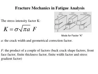
Griffith Criteria • Tensile failure (i.e., Mode I) occurs when the local stress at the most optimally oriented flaw attains a value characteristic of the material • Uniaxial tensile failure strength: • E: Young’s modulus • ν: Poisson’s ratio • γ: energy required to create new crack walls • a: flaw half length • Gc: critical strain energy release rate
Griffith Criteria • The Griffith criterion and Mohr circles showing (a) Uniaxial tensile failure, σ1 = 3T0 (at σ2 = T0); (b) uniaxial compressive failure, σ1 = 8T0 (at σ2 = 0); and (c) transition stress from crack growth to frictional sliding, σ1 ≅ 4.5T0. • Pure Mode I failure is predicted where the Mohr circle touches the Griffith criterion at exactly one point
Andersonian Fault Mechanics • E. M. Anderson’s first work on the subject of faulting was in 1905, but he is probably best known for his 1951 book (at right). • First proposed that faults are brittle fractures that occur according to the Coulomb criterion. • Divided faults into 3 classes that form depending on the ratio and orientation of principle stresses: • Normal • Thrust or reverse • Strike-slip
Andersonian Fault Mechanics • For all faults: • σ1 > σ2 > σ3 • Fault forms at an angle θ from σ1 • Thrust fault: • σ1 = σH • σ2 parallel to fault strike • σ3 = σv • Strike-slip fault • σ1 = σH • σ2= σv • σ3 = σh • Normal fault • σ1 = σv • σ2parallel to fault strike • σ3 = σh
Andersonian Fault Mechanics • σv = weight of overburden or ρgz • Cube of rock subjected to vertical stress from overburden will extend in x and y directions (horizontal): Poisson ratio • ν = horizontal expansion/vertical shortening • ν< 0.5 • The coefficient of friction and fault dip are related in order to minimize horizontal stress resolved on the fault plane. • To determine the fault dip from vertical for each dip-slip fault type, we use this equation: • Tan2θ = 1/μ • θ = 0.5(tan-1(1/μ))
This plot shows the minimum differential stress required to initiate sliding on a normal, strike-slip, and thrust fault. • Which line is which? Why? • Thrust faults require 16x more stress to rupture than normal faults and 2.6 x more stress than strike-slip faults. • How does this relate to earthquakes? THRUST STRIKE- SLIP NORMAL
Strain • Stress σ causes strain ε • Strain is non-dimensional • Strain is any change in shape, volume, or orientation of a rock volume • Contractional normal strain perpendicular to σ1 and extensional normal strain perpendicular to σ3 • Normal faulting results in extensional strain (horizontal) • Thrust faulting results in contractional strain (horizontal) • Extensional strain (vertical)
Strain • Strain can be calculated by doing a 1D traverse across a set of faults • Calculate strain based on fault geometry
Strain • Extension • Need depth of graben (d) • Fault dip angle (θ) • h = d/tanθ • Add these up for every fault in the traverse
Strain • This method of calculating strain can miss some faults. • In addition, the traverse may miss locations of maximum fault displacement (usually near the center of the fault, but not always). • Thus, better, more accurate methods exist to calculate strain from fault populations. • Seismology to the rescue!
Strain, the right way • Where D is the average displacement, L is the fault length, and H is the down-dip fault height (faulting depth/sinθ), V is the volume of the deformed region (depth of faulting*area of faults), and δ is the fault dip angle • This method includes all mapped faults and is not dependent on the location of 1D traverses.
NORMAL FAULTING http://mesic.astronomie.cz/Prohlidka/mesicni-brazda.php Moon
Planetary Tectonics:Normal Faults Primary extensional morphologies on the planets: • graben • single normal faults Graben are the down-dropped blocks between two antithetic NF. Single normal faults are rare.
Planetary Tectonics:Normal Faults Where are NF found? • Moon • Mars • Venus • Earth • Mercury • Asteroids • Icy satellites
Planetary Tectonics:Normal Faults How do these NF form? • rifting • dike intrusion • basin loading • regional-scale uplift • tidal stresses • impacts
Rare individual NF Basin loading or from Imbrium? Grew from small segments from S to N opposite direction if formed by Imbrium impact Likely not from basin loading, since it is on the edge of Nubium, too young, and straight Planetary Tectonics:Normal Faults Moon
Planetary Tectonics:Normal Faults • Valles Marineris: the largest canyon system in the solar system • rift valley • 10 km wide • 5 km deep • 3000 km long • Crustal extension along large-scale normal faults related to Tharsis volcanism and heat production Mars
Planetary Tectonics:Normal Faults • Pantheon Fossae • set of ~radial graben near center of Caloris basin, Mercury • Hypotheses: • Formed as a result of the impact • Dike intrusion • Basin interior uplift • PF formed in response to a dome with a R = 300 km, T = 150 km, and a maximum uplift of 10 km [Klimczak et al. (2011)] 40 km Mercury
Planetary Tectonics:Normal Faults • Grooves • long • parallel • narrow • tidal or thermal stresses? • impact-related? http://apod.nasa.gov/apod/image/0911/PSP_007769_9010_IRB_Stickney.jpg Phobos (Mars)
Planetary Tectonics:Normal Faults • Venusian chasma (rift) • very long • high relief • relatively young features? • Regional-scale crustal extension along antithetic normal faults • Associated with volcanoes, likely due to uplift from underlying plume ~100 km http://nssdc.gsfc.nasa.gov/imgcat/hires/mgn_c130n279_1.gif Venus
Planetary Tectonics:Normal Faults Earth • Basin and Range province formed by crustal extension along antithetic normal faults forming graben (basin) and horsts (range) from subduction of the East Pacific Rise ~15 Ma http://rst.gsfc.nasa.gov/Sect6/nv.jpg http://rst.gsfc.nasa.gov/Sect6/38Basin_Range_aerialsm.jpg
THRUST FAULTING ~40 km Mercury
Planetary Tectonics:Thrust Faults Primary contractional morphologies on the planets: • wrinkle ridges • lobate scarps Wrinkle ridges are blind thrust faults, often in areas of interbedded lava and regolith and/or pyroclastic material. Lobate scarps are surface-cutting thrust faults that occur in mechanically homogenous terranes. http://www.nasa.gov/images/content/475507main_lobate_scarp_thrust_fault_graphic.jpg
Planetary Tectonics:Thrust Faults Where are TF found? • Moon • Mars • Venus • Earth • Mercury • Asteroids
Planetary Tectonics:Thrust Faults How are these TF formed? • basin loading • lava cooling and contraction • impacts • (global contraction)
Planetary Tectonics:Thrust Faults • Hesperia Planum • type locality for Hesperian epoch • Lava plains likely interbedded with pyroclastic deposits (from Tyrrhena Patera) • Multiple generations of WR indicate several temporally and spatially distinct episodes of compression ~25 km http://www.lpi.usra.edu/publications/slidesets/redplanet2/slide_9.html Mars
Planetary Tectonics:Thrust Faults • Wrinkle ridges in Mare Crisium • Show a buried crater • Can give an idea of depth of mare fill in Crisium Basin ~15 km http://spacefellowship.com/news/art19041/crisium-s-region-of-interest.html Moon
Planetary Tectonics:Thrust Faults • Venusian wrinkle ridges appear to preferentially form in topographic lows • Compressional stress likely from cooling and contraction in a topographic low • Some WR terranes show more than one orientation of WR • more complicated and varied stress field ~40 km http://www.sciencemag.org/content/286/5437/87/F1.large.jpg Venus
Planetary Tectonics:Thrust Faults • Lobate scarp (Hinks Dorsum) on the asteroid Eros • Modeling gives fault parameters • Depth = 250 m • 90 m of offset • Near-surface shear strength ~1 – 6 MPa • Formed by impact-induced compression ~6 km Watters et al., GRL 2011 Eros
Planetary Tectonics:Thrust Faults • Himalayan fold-and-thrust belt • Large-scale continental collision • Began ~50 Ma • Peak of Everest is LIMESTONE • ~2400 km of India already ‘lost’ • 1500 km of India subducted over the next 10 Myr ~300 km http://www.visit-himalaya.com/gifs/nepal-everest2.jpg Earth