Download
1 / 21
220 likes | 246 Vues
SEISMIC & WIND ANALYSIS OF BRIDGES. Based on Recommended LRFD guidelines for Seismic design on Highway bridges (May 2006 ed.). WIND ANALYSIS OF BRIDGES. Pressure specified shall be assumed to be caused by a base design wind velocity V B = 160 Km/hr.

E N D
SEISMIC & WIND ANALYSIS OF BRIDGES • Based on Recommended LRFD guidelines for Seismic design on Highway bridges (May 2006 ed.)
WIND ANALYSIS OF BRIDGES • Pressure specified shall be assumed to be caused by a base design wind velocity VB = 160 Km/hr. • For bridges or parts of bridges more than 10,000 mm above low ground or water level, design wind velocity VDZ should be adjusted according to: Where VDZ = Design wind velocity at elevation Z (Km/hr)V10 = Wind velocity at 10 000 mm above low ground or design water level (Km/hr)VB = Base wind velocity of 160 Km/hr at 10 000 mm heightZ = Height of structure at which wind loads are being calculated as measured from low ground or water level > 10 000 mmV0 = Friction velocity a meteorological wind characteristic taken as specified in Table below Z0 = Friction length of upstream fetch a meteorological wind characteristic taken as specified in Table below.V10 may be established from basic wind speed charts available for various recurrence intervals, site specific wind surveys or in absence of better criteria, the assumption that V10 = VB = 160 Km/hr
WIND ANALYSIS OF BRIDGES • WIND PRESSURE ON STRUCTURES • The total wind loading shall not be taken less than 4.4 N/mm in the plane of windward chord and 2.2 N/mm in the plane of leeward chord of truss or arch components and not less than 4..4 N/mm on beam and girder spans.
LOADS FROM SUPERSTRUCTURES WIND ANALYSIS OF BRIDGES • Where wind is not taken as normal to the structure, the base wind pressures PB for various angles of wind direction may be taken as specified in table below and shall be applied to the single place of exposed area. The skew angle shall be taken as measured from perpendicular to the longitudinal axis. The wind direction for design shall be that which produces the extreme force effect on the component under investigation. • The transverse and longitudinal pressures shall be applied simultaneously.
WIND ANALYSIS OF BRIDGES • FORCES APPLIED DIRECTLY TO THE SUBSTRUCTURE The transverse and longitudinal forces to be applied directly to the substructure shall be calculated from an assumed base wind pressure of 0.0019 MPa. For wind direction taken skewed to the substructure, this force shall be resolved into components perpendicular to the end and front elevations of the substructure. The component perpendicular to the end elevation shall act on exposed substructure area as seen in end elevation, and the component perpendicular to the front elevation shall act on the exposed areas and shall be applied simultaneously with the wind loads from superstructure. WIND PRESSURES ON VEHICLES When vehicles are present the design pressure should be applied on both structure and vehicles. Wind pressure on vehicles shall be represented by an interruptible moving force of 1.46 N/mm acting normal to and 1800 mm above the roadway and shall be transmitted to the structure. When wind on vehicles is not taken as normal to the structure, the components of normal and parallel force applied to the live load may be taken as specified in the table below
Example: WIND ANALYSIS
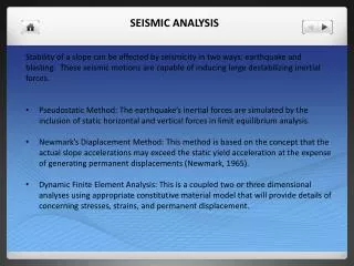
SEISMIC ANALYSIS OF BRIDGES • IMPORTANCE CATEGORIES • Critical bridges (open to all vehicles immediately after EQ. 2500 year return period) • Essential bridges (open to emergency / defense / security vehicles immediately after EQ. 475 year return period event) • Other bridges SEISMIC PERFORMANCE ZONE
SEISMIC ANALYSIS OF BRIDGES SOIL PROFILE TYPE SOIL PROFILE I: Rock either shale or crystalline in nature. SOIL PROFILE II: Stiff cohesive or deep cohesion less soil. SOIL PROFILE III: Soft to medium stiff clay and sand. SOIL PROFILE IV: Soft clay or silt. ELASTIC SEISMIC RESPONSE COEFFICIENT
SEISMIC ANALYSIS OF BRIDGES • For bridges on Soil profile III & IV & in areas where A is not less than 0.3, Csm need not exceed 2.0 A. • For soil profiles III & IV and for modes other than fundamental mode that have period less than 0.3 s, Csm shall be taken as If period of vibration for any mode exceeds 4.0 s the value of Csm for that mode shall be taken as
SEISMIC ANALYSIS OF BRIDGES • As per AASHTO LRFD Bridges in seismic zone 1 need not be analyzed for seismic loads regardless of their importance and geometry. However the minimum requirements in sections 4.7.4.4 & 3.10.9 shall be applied. • Seismic analysis for is not required for single span bridges, regardless of the seismic zone.
SEISMIC ANALYSIS OF BRIDGES Seismic analysis required / not required • * = No seismic analysis is required • UL = Uniform load elastic method • SM = Single mode elastic method • MM = Multimode elastic method • TH = Time history method
SEISMIC ANALYSIS OF BRIDGES Regular & Irregular bridges Bridges satisfying the above table requirements may be regarded as Regular bridges otherwise Irregular bridges. Curved bridges comprise of multi simple-span shall be considered as irregular bridge if subtended angle in plan is greater than 20o. Such bridges shall be analyzed by either multimode elastic method or time history method.
A curved continuous girder bridge may be analyzed as if it were straight, provided all of the following requirements are meet.1. The bridge is regular as defined in table above except that for a two span bridge the maximum span length ratio from span to span must not exceed 2.2. The subtended angle in plan is not greater than 90 deg.3. The span lengths of the equivalent straight bridge are equal to the arc lengths of the curved bridge.If the requirements are not satisfied then the curved continuous girder-bridge must be analyzed using the actual curved geometry. SEISMIC ANALYSIS OF BRIDGES
SEISMIC ANALYSIS OF BRIDGES Where Po = uniform load arbitrarily set = 1 (N/mm) Vs(x) = Deformation corresponding to Po (mm) W(x) nominal unfactored dead load of the bridge superstructure and tributary substructure (N/mm) Then calculate the time period of the bridge structure g = Acceleration due to gravity (m/sec2)