Download
1 / 5
50 likes | 150 Vues
Installation step 4. (3 days). B. A. A. Install temporary support It’s made of 2 halves; the upper one is brought into position through rotation about axis “A” (to avoid risks for the beam pipe)

E N D
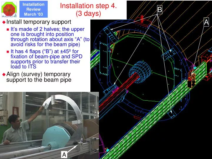
Installation step 4. (3 days) B A A • Install temporary support • It’s made of 2 halves; the upper one is brought into position through rotation about axis “A” (to avoid risks for the beam pipe) • It has 4 flaps (“B”) at ±45º for fixation of beam-pipe and SPD supports prior to transfer their load to ITS • Align (survey) temporary support to the beam pipe
Installation step 5. (4 days) • Spoke structure reduces material in front of FMDs and allows for visual inspection • Test FMDs • FMDs have pigtails up to the outer edge of the 3rd cone • Remove 3rd cone lifting tools FMD – Si1 Dummy 3rd cone • Fix support for beam pipe and FMD (“3rd cone”) to temporary support • The 3rd cone is made of two halves containing the FMDs • lifting tools allow for slow and accurate positioning of 3rd cone Lifting tool
Installation step 6. (2 days) • Mount and adjust monitoring system of bellow movements • Responsibility ALICE • Non-touching capacitive sensors are proposed • Mount and adjust 1st support to the beam pipe • Responsibility AT/VAC • Survey Lifting tool
Installation step 7. (8 days) Temporary support 3rd cone SPD services Section 2 SPD cone • Install the two SPD half-cylinders (Resp. ALICE) • Two half cylinder/cones • Specific installation tools are being designed • SPD services (cables, fibres & capillaries) are pre-assembled in the cones • Fix the two, coupled, SPD half-cylinders to temp. support, above the 3rd cone, using a 2nd series of bolts & precision plugs • SPD fixed in cantilever mode to temp. support, SPD pigtails on RB24 side unconnected • Remove section 2 of beam pipe support (Resp. AT/VAC)
Installation step 8. (7 days) Temp.Support • Mount and adjust 2nd support to the beam pipe (resp. AT/VAC) • Survey • Outer ITS, SPD & beam pipe are now an integral unit SPD SDD SSD TPC/C4 • Slide outer ITS onto SPDs (Responsibility ALICE) • Transfer load of SPD and 3rd cone (beam pipe) from temporary support to ITS • Connect SDD and SSD on RB26 side • Final fixation of SPD pigtails on RB24 side to ITS cone