Download
1 / 21
240 likes | 489 Vues
Monolithic Reactors for Environmental Catalysis. 朱信 Hsin Chu Professor Dept. of Environmental Eng. National Cheng Kung University. 1. Introduction. Minimize the pressure drop associated with high flow rates

E N D
Monolithic Reactors for Environmental Catalysis 朱信 Hsin Chu Professor Dept. of Environmental Eng. National Cheng Kung University
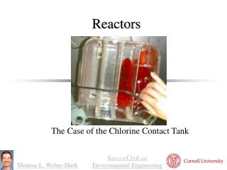
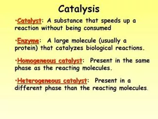
1. Introduction • Minimize the pressure drop associated with high flow rates • Allow the process effluent gases to pass uniformly through the channels of the honeycomb
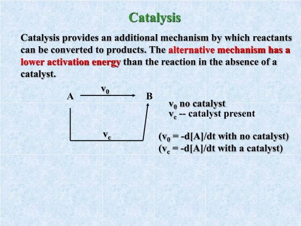
2. Chemical Kinetic Control • To be controlled by chemical kinetics rather than by diffusion to or within the catalyst pore structure while the geses are cold • When the surface becomes sufficiently hot, the rate will be determined by mass transfer. • In the laboratory, when screening a large number of catalyst candidates, it is important to measure activity at low conversion levels to ensure that the catalyst is evaluated in the intrinsic or chemical rate-controlling regime. • Good laboratory practice is to maintain all conversions below 20% for kinetic measurements. (adiabatic)For highly exothermic reactions (i.e., △H > 50kcal/mol), measurements should be made at conversions no greater than 10%.
A material balance across any reactor gives the following equation assuming one-dimensional, plug flow, steady-state operation: where v = velocity (cm/s) C = molar concentration [(g‧mol)/cm3] z = length (cm) r = rate of reaction [(g‧mol)/(cm3‧s)] • When the conversion or the reactant concentration is low, the reactor is considerd isothermal; hence
Assume the oxidation of ethane to CO2 and H2O in a large excess of O2 in a fixed bed of catalyst:We can assume that the rate is independent of O2. • It obeys first-order kinetics (pseudo-zero-order in O2), so the rate is expressed as:where k’ = the apparent rate constant • Integrating from the reactor inlet (i) to outlet (o) gives:where t = actual residence time (s)
t = • Volumetric hourly space velocity (VHSV) VHSV = • The rate expression then becomes:By varying the space velocity, the change in conversion can be determined.The slop of the plot yields the k” of the reaction at STP. • Next slide (Fig. 4.1)Ethane conversion versus temperature at different space velocities.
3. Bulk Mass Transfer • When experiments are conducted with extremely active catalyst or at high temperatures, diffusional effects are introduced, and the intrinsic kinetics of the catalytic material is not determined accurately. • The activation energy will decrease as pore diffusion and bulk mass transfer become more significant. • Stationary environmental abatement processes are designed to operate in the bulk mass transfer regime where maximum conversion of the pollutant to the nontoxic product is desired. • Diffusion processes have small temperature dependency (low activation energies).Chemical-controlled reactions have a high degree of dependence on temperature (high activation energies).
Important benefit of diffusion processes:the physical size and other geometric parameters of the honeycomb for a required conversion can be obtained using fundamental parameters of mass transfer.Where kg = mass transfer coefficient (cm/s) a = geometric surface area per unit volume (cm2/cm3) C = reactant gas phase concentration [(g‧mol)/cm3] • Integrating, Fractional conversion = 1- exp[-(kgat)]
Some dimensionless numbers where D = diffusivity of pollutant in air (cm2/s) W = total mass flowrate to honeycomb catalyst (g/s) A = frontal area of honeycomb (cm2) dch= hydraulic diameter of honeycomb channel (cm)ρ = gas density at operating conditions (g/cm3) μ= gas viscosity at operating conditions (g/s‧cm) ε= void fraction of honeycomb, dimensionless • Equation on last slide becomes:Fractional conversion = 1- exp where L = honeycomb length (cm)
Example 1 Calculation for Mass Transfer ConversionThe removal of propane (C3H8) in a stream air at 300℃ and atmospheric pressure with:Flow rate, W= 1000 lb/h (126g/s)Diameter of monolith, D=6 in. (15.24 cm)Length of monolith, L=6 in.(15.24 cm)Area of monolith, A=182.4 cm2Monolith geometry, 100 cpsi (15.5 cells/cm2)C3H8 feed fraction, X=1000 vppm (volume parts per million) • Sol: From the literature (Lachman and McNally, 1985) dch = 0.083 in. (0.21cm) ε=0.69 a = 33 in.2/in.3 (13 cm2/cm3)
Using Hodgman’s (1960) Handbook of Chemistry and Physics The density (ρ) and viscosity (μ) of air :ρ at 300℃ = 6.16 × 10⁻⁴ g/cm3μ at 300℃ = 297 × 10-6 g/s‧cmTherefore, • To utilize Fig. 4.2, the following term must be determined:
From Bird et al., 1960, the diffusivity for a binary system:where M = molecular weight of species, A=air; B=C3H8 [g/(g‧mol] P = total pressure (atm)σAB= collision diameter for binary system (Å) T = absolute operating temperature (K) = collision integral for binary system, dimensionless • Using Table B-1 from Bird et al., 1960:For air: MA = 28.97, σA=3.617Å, For C3H8: MB=44.09, σB=5.061Å,where σ and are Lennard-Jones parameters for the single components.
The binary system: • Using this value and Table B-2 from Bird (1960), • Therefore,
Using Figure 4.2, NRedch/L=9.75→Nsh/Nsc0.56=3.8Therefore, Nsh=4.4 • Fractional conversion = = = 0.736 = 73.6% (done)
4. Reactor Bed Pressure Drop • Pressure drop (△P)a. flow contracts within the restrictive channel diameterb. washcoat on the surface of the honeycomb channel creates friction • The basic equation for △P derived from the energy balance:where P = total pressure (atm) f = friction factor, dimensionless gc = gravitational constant (980.665 cm/s2) υ= velocity in channel at operating conditions (cm/s) ρ= gas density at operating conditions (g/cm3) • Next slide (Fig. 4.3)Friction factor correlation to NRe
The velocity in the channel (υ)where ε = void fraction (percent open frontal area of the honeycomb) A = cross-sectional area of honeycomb • Simplify the basic equation for △P • Next slide (Fig. 4.4) △P versus flow rate To select the optimum honeycomb geometry (volume, cross-sectional area, length, cpsi, etc.) for a given application