Download
1 / 8
80 likes | 279 Vues
MTF SLIT. COMPONENTS. Adjusting Blocks and Mounting Plate. Steel Blocks. Clamps. Shims. Slide Blocks. Two Blocks of Oil Hardening Steel are separated by shims 100um thick. This forms the slit for MFT measurements.

E N D
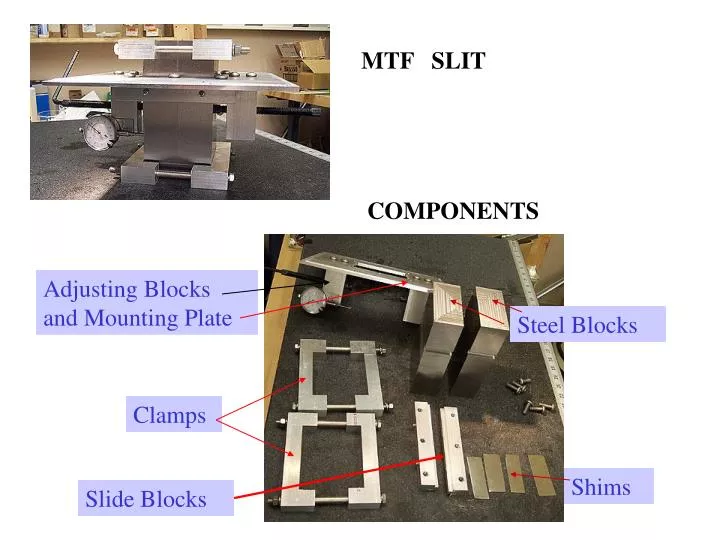
MTF SLIT COMPONENTS Adjusting Blocks and Mounting Plate Steel Blocks Clamps Shims Slide Blocks
Two Blocks of Oil Hardening Steel are separated by shims 100um thick. This forms the slit for MFT measurements. The blocks are secured via two sets of clamps made from aluminum blocks and stainless steel bolts
The steel blocks need to be adjustable so the slit can be centered under the XRAY beam. To allow adjustment, the bocks have a groove which allow them to move along a ridge on the slide blocks.
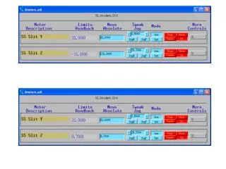
The actual adjustment is made by turning the left and right adjusting screws. A dial indicator is mounted on one of the adjusting blocks to determine the amount of movement.
The steel blocks are pulled together with the stainless steel shims separating them by 100 microns. The blocks are clamped loosely at the bottom. Then the sliding blocks are placed in the grooves of the steel blocks. The dial indicator is bolted to one of the adjusting blocks. Adjusting screws are placed in the threaded adjusting blocks. The adjusting blocks are then bolted to the underside of the mounting plate.
The mounting plate ready for assembly. The mounting plate is placed over top of steel blocks.
The top clamps are set in place and tightened.