Download
1 / 12
120 likes | 308 Vues
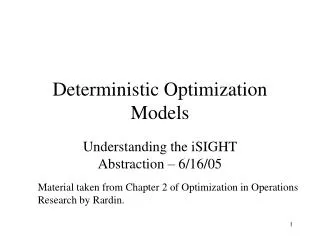
Network Optimization Models: Maximum Flow Problems. In this handout: The problem statement Augmenting path algorithm for solving the problem. A. 4. 4. 6. B. O. D. 5. 5. T. 4. 4. 5. C. Maximum Flow Problem. Given : Directed graph G=(V, E),

E N D
Network Optimization Models:Maximum Flow Problems • In this handout: • The problem statement • Augmenting path algorithm for solving the problem
A 4 4 6 B O D 5 5 T 4 4 5 C Maximum Flow Problem • Given: Directed graph G=(V, E), Supply (source) node O,demand (sink) node T Capacity function u: E R . • Goal: Given the arc capacities, send as much flow as possible from supply node O to demand node T through the network. • Example:
Towards the Augmenting Path Algorithm • Idea: Find a path from the sourceto the sink, and use it to send as much flow as possible. • In our example, 5 units of flow can be sent through the path O B D T ; Then use the path O C T to send 4 units of flow. The total flow is 5 + 4 = 9 at this point. • Can we send more? A 4 4 5 5 B 5 O D 5 6 T 4 5 4 4 4 C 5
Towards the Augmenting Path Algorithm • If we redirect 1 unit of flow from path O B D T to path O B C T, then the freed capacity of arc D T could be used to send 1 more unit of flow through path O A D T, making the total flow equal to 9+1=10 . • To realize the idea of redirecting the flow in a systematic way, we need the concept of residual capacities. A 1 1 4 4 4 5 5 4 B 5 O D 5 6 T 4 5 4 4 1 5 4 C 5
Residual capacities 5 D B 6 • Suppose we have an arc with capacity 6 and current flow 5: • Then there is a residual capacity of 6-5=1 for any additional flow through B D . • On the other hand, at most 5 units of flow can be sent back from D to B, i.e., 5 units of previously assigned flow can be canceled. In that sense, 5 can be considered as the residual capacity of the reverse arc D B . • To record the residual capacities in the network, we will replace the original directed arcs with undirected arcs: 5 1 B The number at B is the residual capacity of BD; the number at Dis the residual capacity of DB. D
A 0 4 4 0 5 0 6 B 0 O D 5 0 4 4 T 0 0 0 5 C Residual Network • The network given by the undirected arcs and residual capacities is called residual network. • In our example, the residual network before sending any flow: Note that the sum of the residual capacities on both ends of an arc is equal to the original capacity of the arc. • How to increase the flow in the network based on the values of residual capacities?
Augmenting paths • An augmenting path is a directed path from the source to the sink in the residual network such that every arc on this path has positive residual capacity. • The minimum of these residual capacities is called the residual capacity of the augmenting path. This is the amount that can be feasibly added to the entire path. • The flow in the network can be increased by finding an augmenting path and sending flow through it.
5 0 6 0 5 0 A 0 5 1 B 5 O D 0 5 T C Updating the residual network by sending flow through augmenting paths Continuing with the example, • Iteration 1: O B D T is an augmenting path with residual capacity 5 = min{5, 6, 5}. • After sending 5 units of flow through the path O B D T, the new residual network is: 0 4 4 0 4 4 0 0 0 5
0 A 4 4 1 B O D 4 T 0 0 5 C Updating the residual network by sending flow through augmenting paths • Iteration 2: O C T is an augmenting path with residual capacity 4 = min{4, 5}. • After sending 4 units of flow through the path O C T, the new residual network is: 0 4 4 0 0 5 1 5 0 5 4 0
A 0 1 4 3 3 4 0 1 1 2 B 4 5 O D 3 4 T 4 5 0 1 0 1 C Updating the residual network by sending flow through augmenting paths • Iteration 3: O A D B C T is an augmenting path with residual capacity 1 = min{4, 4, 5, 4, 1}. • After sending 1 units of flow through the path O A D B C T , the new residual network is: 0 5 0 5 0 4
Terminating the Algorithm:Returning an Optimal Flow • There are no augmenting paths in the last residual network. So the flow from the source to the sink cannot be increased further, and the current flow is optimal. • Thus, the current residual network is optimal. The optimal flow on each directed arc of the original network is the residual capacity of its reverse arc: flow(OA)=1, flow(OB)=5, flow(OC)=4, flow(AD)=1, flow(BD)=4, flow(BC)=1, flow(DT)=5, flow(CT)=5. The amount of maximum flow through the network is 5 + 4 + 1 = 10 (the sum of path flows of all iterations).
The Summary of the Augmenting Path Algorithm • Initialization: Set up the initial residual network. • Repeat • Find an augmenting path. • Identify the residual capacity c* of the path; increase the flow in this path by c*. • Update the residual network: decrease by c* the residual capacity of each arc on the augmenting path; increase by c* the residual capacity of each arc in the opposite direction on the augmenting path. Until no augmenting path is left • Return the flow corresponding to the current optimal residual network