Download
1 / 47
470 likes | 690 Vues
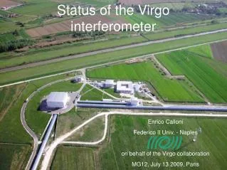
The commissioning of the Virgo interferometer. H. Heitmann Observatoire de la C ô te d’Azur, Nice for the VIRGO collaboration. Evolution of commissioning Upgrades Recent commissioning activities Outlook. Status of commissioning before shutdown. Commissioning sensitivity evolution.

E N D
The commissioningof the Virgo interferometer H. Heitmann Observatoire de la Côte d’Azur, Nice for the VIRGO collaboration • Evolution of commissioning • Upgrades • Recent commissioning activities • Outlook
Commissioning sensitivity evolution Single arm Single arm Single arm Recombined Recycled Recycled Recycled Run C6 duty cycle 90% 40 h lock Run C7 duty cycle 64% 14 h lock
Problems with configuration up to C7 • Fringes due to backscattering in mode cleaner • => Operate with reduced power (10%) • Non-monolithic, curved power recycling mirror • Resonances => Control problems • Shift sensitivity => alignment drifts
Recent upgrades • New power recycling mirror • New injection bench
VIRGO layout Power recycling mirror Injection bench (IB)
Old power recycling mirror 350 mm 120 mm R=4100 mm • PR mirror is • non-monolithic • curved (part of beam matching telescope) Incident Beam • Translations induce • misalignment and jitter noise • flat mirror PR mirror transfer function
New power recycling mirror • Monolithic mirror • No more internal resonances in the control band !! • Flat surfaces • => no more lens effect (no more part of input telescope) • => larger beam coming out of injection bench • => parabolic telescope needed on IB Old New PR mirror transfer function
Fringes in the interferometer Laser Frequency Noise Hz Power Recycling mirror misaligned Power Recycling mirror aligned Time
Origin of the fringes Backscattering in the mode cleaner Laser light Backscattered light Injected power lowered to 700 mW for enabling power recycling (C7 configuration) Faraday Isolator needed on the injection bench for full power operation
Old injection bench 10% reflectivity mirror
New injection bench • Main requirements: • Faraday isolator • Parabolic output telescope • Thinner suspension wires more suitable resoance frequencies
New injection bench (OptoCad design) To interferometer Parabolic output telescope Faraday isolator Mode cleaner Design and realization EGO optics group From laser
New injection bench (below) Reference cavity
New injection bench status • Bench is • installed • aligned • controlled • Beam • output power 7 W (10x C7) • matching: coupling into arm cavities 95-97%
Some recent commissioning activities • The variable finesse locking technique • Mode cleaner mirror radiation pressure • Suspension improvements • New injection system autoalignment
Locking: Step 1 Recombined interferometer WE • Power recycling mirror misaligned • => no signal mixing • Each cavity locked independently • ITF output at « grey fringe » (50%) Controls NE North cav. transmission P WE West cavity transmission P BS Dark fringe power DC West arm WI PR BS NI NE North arm 50%
Locking: Step 2 Recombined interferometer WE • Laser locked on ITF common mode • very high bandwidth loop • => get rid of dominating • common mode signal Controls NE-WE North cav. transmission P BS Dark fringe power DC laser Recycling cavity pick-off P PR ITF reflection (3) P West arm WI ITF common mode PR BS NI NE North arm 40%
Locking: Step 3 Recycled interferometer WE • Power recycling mirror aligned Controls NE-WE North cav. transmission P BS Dark fringe power DC laser Recycling cavity pick-off P PR ITF reflection (3) P West arm WI ITF common mode PR BS NI NE North arm 40%
Locking: Step 4 Recycled interferometer WE • Stepwise going down to dark fringe Controls NE-WE North cav. transmission P BS Recy.cav. pick-off Q laser Recy.cav. pick-off P PR ITF reflection (3) P West arm WI ITF common mode PR BS NI NE North arm 5%
Locking: Step 5 Recycled interferometer WE • Dark fringe reached Controls NE-WE Dark fringe P BS Recy.cav. pick-off Q laser Recy.cav. pick-off P PR ITF reflection (3) P West arm WI ITF common mode PR BS NI NE North arm 0%
Mode cleaner mirror:radiation pressure effect y Frequency increase MC locked full power MC locked 60% power MC unlocked x: 2.13 ->1.97 Hz y:1.27 -> 2.0 Hz • Mode position changes with mirror alignment • extra torque • resonance frequency change Problem: • Autoalignment loops became unstable • Corrector adaptation was needed mirror dimensions: 30x80 mm 360 grams
Suspension: recent problems and solutions • Mirror excitation with bad weather • less stable lock Changed suspension top stage control seismic acceleration noisy day calm day 30 mHz Contribution to control ground-based sensors accelerometer Ground-independent control above 30 Hz Micro-seismic peak (sea waves) DAC noise on mirror actuation coils Hierarchical control Rearrange forces going to the suspension Switch to low-noise coil drivers (See talk by G. Losurdo)
Injection system autoalignment Mode cleaner transmitted power fluctuations • Old system Idea: if IB is rigid, no misalignments (turned out not to be true) • IB under local control • New system • Beam aligned on fixed mechanical reference (external bench) Mode cleaner fully aligned on beam Autocentering of beam onto MC end mirror Future enhancement Beam aligned on 3 km target 10% 2004
Old injection system autoalignment layout MC mirror autoalignment Beam autoalignment Inj.B. local control Injection bench Ref. cav. autoalignment IB Coils MC AA Picomotors Wavefront sensors Piezos MC mirror Laser Ref. cav. -- -- -- M6 M5 MATRIX MATRIX
New injection system autoalignment layout Beam autoalignment Inj.B. autoalignment MC mirror autoalignment Injection bench Ref.cav. autoalignment Beam prealignment IB Coils RFC AA MC IB AA Picomotors DC position sensors Wavefront sensors Piezos MC mirror Laser MATRIX Ref. cav. -- -- -- -- M6 M5 MATRIX MATRIX
Present status Thermal effects in rec. cavity Carrier power Sideband power 0 Time • Full locking of interferometer • 1-2 hours locking periods • or 5 minutes … • Thermal effects • Affect recycling cavity stability • (modulation sidebands drop) • 30-50 Hz burst events (skeephs) • Locking stability problems • Misalignment sensitivity? • Hasten full autoalignment (5/10 d.o.f. OK) 2h
Next steps • Improve sensitivity • Low frequency • control noise (alignment) • modulation frequency tuning (servo) • Medium frequency • scattered light • acoustic shielding in laser lab • High frequency • increased power • new low-noise HF modulation generator • New MC mirror • better surface quality • lower losses • larger, heavier? • avoid radiation pressure problems • facilitate control • ...
End End
Old injection bench (OptoCad design) To interferometer Mode cleaner 10% reflectivity mirror for power reduction From laser
Duty Cycle of last two commissioning runs C6 (14 days Aug. 2005) C7 (5 days Sept. 2005) 40 hours locked 14 hours locked
Suspension: recent problems wind speed susp displacement • 1. Mirror excitation in windy conditions • => more frequent unlocks when weather is bad • 2. DAC noise on mirror actuation coils • High force needed for lock acquisition • => bad DAC dynamics in steady conditions (low force) seismic acceleration noisy day calm day Micro-seismic peak (sea waves)
Suspension: inertial damping modification • Inertial damping • Inverted pendulum top platform is immobilized by • HF accelerometers (inertial sensors) • LF LVDT’s (ground based) => introduce seismic noise • Solution • Reduced HF/LF cross-over frequency to 30 mHz • Not so simple ... (see G. Losurdo’s talk) accelerometer 30 mHz H(s) L(s) LVDT L+H = 1 LVDT = linear variable differential transformer
Suspension: hierarchical control • Initial condition: • lock acquisition • all force goes to mirror • Static condition: • interferometer locked • force split according to frequency bands DC-0.01 Hz Tide control 0.01-5 Hz DAC noise 5-50 Hz After lock acquisition: reduction of mirror actuator gain => reduction of DAC noise
1.4 Mo coalescence detection range M31 (Andromeda) 700 kpc C7 (19 Sept 05) Environmental disturbance re-injection through the control system C6 (12 Ago 05)
Mirror centering • Needed because of astigmatism and suspected beam clipping • Advantage: learned techniques for mirror centering • Necessary for reducing alignment noise which limits us at low frequencies • Two techniques used • Visual centering • Where possible… • Mirror shaking at natural resonance • Find frequency in longitudinal motion (locking error signal) x
Local control camera image observation of diffused beam spot while moving mirror Beam splitter visual centering Mirror Coil ~ 2 cm ~ 1.5 cm • Before centering • After centering