Download
1 / 9
120 likes | 382 Vues
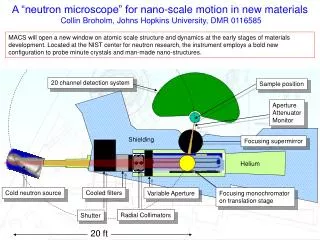
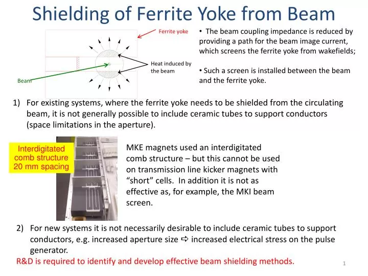
Shielding of Ferrite Yoke from Beam. Interdigitated comb structure 20 mm spacing. The beam coupling impedance is reduced by providing a path for the beam image current, which screens the ferrite yoke from wakefields; Such a screen is installed between the beam and the ferrite yoke.

E N D
Shielding of Ferrite Yoke from Beam Interdigitatedcomb structure 20 mm spacing • The beam coupling impedance is reduced by providing a path for the beam image current, which screens the ferrite yoke from wakefields; • Such a screen is installed between the beam and the ferrite yoke. For existing systems, where the ferrite yoke needs to be shielded from the circulating beam, it is not generally possible to include ceramic tubes to support conductors (space limitations in the aperture). Ferrite yoke MKE magnets used an interdigitated comb structure – but this cannot be used on transmission line kicker magnets with “short” cells. In addition it is not as effective as, for example, the MKI beam screen. Heatinduced by the beam Beam For new systems it is not necessarily desirable to include ceramic tubes to support conductors, e.g. increased aperture size increased electrical stress on the pulse generator. R&D is required to identify and develop effective beam shielding methods.
MKI Shielding of Ferrite Yoke • The eight LHC Injection (MKIs) magnets upgraded during LS1 are NOT expected to suffer from problems related to beam induced power deposition, of the ferrite yoke, during run 2 of the LHC. However, based on current HL-LHC beam parameters, additional upgrades are required, for implementation during LS2, to avoid problems of the ferrite yoke temperature exceeding the Curie Temperature: • Study further means of further reducing beam induced power deposition: Loverlap 1mm gap between ceramic tube and conducting cylinder (return [ground] busbar side). SS cylinder Ceramic Screen conductors (graded lengths) 3mm gap between ceramic tube and conducting cylinder (HV busbar side) Metallized ceramic End of metallization
Cooling of Ferrite Yoke • Study further means of heat removal from the ferrite yoke, e.g. liquid cooling of HV busbar and/or higher emissivity of vacuum tank (see slide by Wim): MKI vacuum tanks were electopolished (for septa) emissivity of ~0.15. Note: visible light 400nm to 700nm wavelength. Plot courtesyof T. Bardo & S. Calatroni (TE-VSC) TE-VSC have carbon coated SS316-LN and, with a ~600 nm thick coating, achieved emissivities of >0.8 (600nm thick C). A method of applying this to a “large” thank would need to be developed (e.g. by TE-VSC).
Surface Flashover of Ceramic It is thought that “high” pressure caused an electrical breakdown of an MKI in the LHC. Hence surface flashover of the ceramic tube, in a test (“Simi”) tank, is being/will be studied as a function of: Pressure of injected gas; Ionization of gas; Gas species (e.g. H2, H2O, CO, ….) Very important… e.g. could result in a “common mode” failure in all 4 MKIs, at an injection point!
Surface Flashover of Insulators aC 1.4 • Uncoated ceramic has a maximum Secondary Electron Yield (SEY) of ~10. • Coating the ceramic with Cr2O3 or Amorphous Carbon (aC) can reduce the SEY to less than 1.4 (a magic number for the LHC, with 25ns beam). • In addition Cr2O3has been shown, by other researchers, to increase the voltage at which surface flashover occurs. • An order has been placed in industryto develop a technique to apply Cr2O3to the inside of a 3m long (MKI) ceramic tube. A shorter (50cm) long coated tube will be HV tested in the “Simi” tank. • Be careful of other potential problems, e.g. dust (UFOs) Cr2O3
Ferrite Even with improved cooling of the yoke of a kicker magnet, there are advantages (and disadvantages, such as outgassing – see slide by Wim) of using a ferrite with a higher Curie Temperature (e.g. 180˚C, compared to ~120˚C for ferrite presently used). In addition future fast kickers (e.g. for the FCC) may need to provide a stronger field, and hence ferrites with a higher saturation flux-density will be required. Vacuum compatibility of suitable ferrites needs to be checked (by TE-VSC) and a prototype kicker magnet built and tested.
Very High Stability Pulse Power Modulators 1st protype of (low beam impedance, extremely high field uniformity [±0.01%]) striplines Prototype inductive adder A goal, for CLIC (DR), is to develop a kicker system with ±12.5kV (±250A), 160ns duration flattop, pulses with a stability of ±0.02%!! An inductive adder, carefully designed, constructed and using sophisticated modulation techniques, gives promising results: Trigger inputs
High Burst-rate Power Modulator Required for CLIC CR; ~700 kHz burst rate (~100 pulses); 10 kV, 200 A; “Collaboration” started with SLAC (Mark Kemp). • Initial “low” voltage prototype built to demonstrate basic concept: • A variant of the typical induction modulator topology (magnetic material) and full bridge inverter; • Cells produce alternating positive and negative polarity pulses, but load output is single polarity; • Flux alternates direction in the core, enabling pulse train output; Q1 Q2 DC in Q3 Cell 1 To load Q4 DC in Cell 2
High Repetition Rate Marx Generator CLIC requires a high repetition rate (1 kHz, 12.5 kV) pulse generator for RF breakdown studies. A system, based on a Behlke switch, delivered by FPS in 2011, generally works well and has provided very useful statistics for breakdown studies: but the Behlke switch sometimes “dies” (the reason is not fully understood). A replacement system, based on Marx Generator technology, is under discussion with Luis Redondo (Lisbon Superior Engineering Institute, Portugal): The Marx Generator is potentially a very interesting technology for CERN – and can provide a modular, fault tolerant, design with the ability to “shape” pulses.