Download
1 / 16
460 likes | 1.32k Vues
IEC 61230. IEC 61230 Standard defines: Test duration Test method and configuration specific Peak current factor Tolerances IEC 61230 Standard does not define: Specified current test values Pass / Fail rated values. IEC 35kA Rating. IEC 61230 35kA Rated values: J configuration test setup

E N D
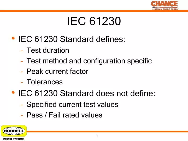
IEC 61230 • IEC 61230 Standard defines: • Test duration • Test method and configuration specific • Peak current factor • Tolerances • IEC 61230 Standard does not define: • Specified current test values • Pass / Fail rated values
IEC 35kA Rating • IEC 61230 35kA Rated values: • J configuration test setup • Rated current – 35kA • Test duration – 17 Cycles • Peak current factor – 2.6 • AC component of test – 115% • Test current @ 115% - 40.3kA • 1st cycle peak current – 104.7kA
IEC 40kA Rating • IEC 61230 40kA Rated values: • J configuration test setup • Rated current – 40kA • Test duration – 17 Cycles • Peak current factor – 2.6 • AC component of test – 115% • Test current @ 115% - 46kA • 1st cycle peak current – 119.6kA
IEC 55kA Rating • IEC 61230 55kA Rated values: • J configuration test setup • Rated current – 55kA • Test duration – 17 Cycles • Peak current factor – 2.6 • AC component of test – 115% • Test current @ 115% - 63kA • 1st cycle peak current – 164.5kA
ASTM F855 • ASTM F855 Standard defines: • Test duration • Specific test current values • Defined X/R values • Cable test lengths • Pass / Fail ratings • ASTM F855 Standard does not define: • Tolerances
ASTM F855 Grade 5 Rating • ASTM F855 Grade 5 rated values: • J configuration test setup • Conductor length – defined at 10ft • Test duration – 15 cycles / 30 cycles • X/R – 1.8 • Withstand rated current @ 15 cycles – 43kA • Ultimate rated current @ 15 cycles – 59kA • Withstand rated current @ 30 cycles – 30kA • Ultimate rated current @ 30 cycles – 42kA
ASTM F855 Grade 6 Rating • ASTM F855 Grade 6 rated values: • J configuration test setup • Conductor length – defined at 10ft • Test duration – 15 cycles / 30 cycles • X/R – 1.8 • Withstand rated current @ 15 cycles – 54kA • Ultimate rated current @ 15 cycles – 70kA • Withstand rated current @ 30 cycles – 39kA • Ultimate rated current @ 30 cycles – 49kA
ASTM F855 Grade 5H Rating • ASTM F855 Grade 5H rated values: • J configuration test setup • Conductor length – defined at 10ft • Rated current – 47kA • Test duration – 15 cycles • X/R – 30 • 1st cycle peak current factor – 2.69 • 1st cycle peak current – 126kA • Last cycle peak current – 70kA
ASTM F855 Grade 7H Rating • ASTM F855 Grade 7H rated values: • J configuration test setup • Conductor length – defined at 10ft • Rated current – 68kA • Test duration – 15 Cycles • X/R – 30 • 1st cycle peak current factor – 2.69 • 1st cycle peak current – 183kA • Last cycle peak current – 101kA
IEC vs ASTM Summary IEC 61230 35, 40, & 55kA Ratings ASTM F855 Grade 5, 6, 5H, & 7H Ratings Test Duration – 15 / 30 cycles X/R – 30 for Grade 5H & 7H Withstand Test Current: Grade 5 – 43kA @ 15 Cycles Grade 5 – 30kA @ 30 Cycles Grade 6 – 54kA @ 15 Cycles Grade 6 – 39kA @ 30 Cycles Grade 5H – 47kA Rated Grade 5H – 126kA Peak 1st Cycle Grade 7H – 68kA Rated Grade 7H – 183kA Peak 1st Cycle Must meet critical current levels above to be certified. • Test Duration – 17 cycles • Peak Current Factor – 2.6 • 1st Cycle Peak Current • 35kA – 104.6kA • 40kA – 119.6kA • 55kA – 164.5kA • No critical pass / fail current value.
X/R Ratio X/R is a ratio determined by the system reactance “X” divided by the system resistance “R” looking back towards the power source at the time of a fault. X/R determines the DC component of a ground fault and will decay quickly to only AC symmetrical component of fault. Full DC offset occurs at the time when the DC component current is equal to the initial peak value of the AC current. A higher X/R ratio will lead to a longer DC offset where as a small X/R ration will lead to a rapid DC offset. High X/R ratios lead to more severe and damaging ground faults versus small ratios. High X/R ratios are useful for testing purposes to push equipment to its ultimate electrical and mechanical ratings and capabilities. Impedance Triangle Apparent Power (kVA) Reactive Power (kVARS) Real Power (kW)
IEC Ground Fault Testing Resulting waveform of 35kA ground fault test using high X/R ratio with peak current at 104.65kA. Full DC offset occurs at the 10th cycle of ground fault.
IEC Duckbill Testing Duckbill Clamp certified to ASTM F855 5H and IEC 61230 35kA Ratings 1st Cycle Peak Current – 104kA, Symmetrical Current 40.3kA Duckbill Test Shot Duckbill Slow Motion Test Shot Duckbill Test Shot w/ Ball Stud Failure Slow Motion Failure of Ball Stud Solution to failure – 25mm Ball Stud torque rating too low for duckbill application. 30mm Ball Stud torque rating sufficient for use with Duckbill Clamp on ground end.
IEC 30mm Ball Stud Clamp Testing 30mm Ball Stud Clamp tested to IEC 61230 55kA Ratings 1st Cycle Peak Current – 164kA, Symmetrical Current 63kA 30mm Ball Stud Clamp Test Shot 30mm Ball Stud Clamp Slow Motion 30mm Ball Stud Clamp Heating Failure 30mm Ball Stud Clamp Heating Failure Slow Motion Solution to failure – Thread inside of Ball Clamp to to increase surface area at bolt to clamp connection and to reduce arcing at bolt.
IEC C-Clamp Testing 4” C-Clamp tested to IEC 61230 40kA Ratings 1st Cycle Peak Current – 119kA, Symmetrical Current 46kA 4” C-Clamp Test Shot 4” C-Clamp Slow Motion Test Shot 4” C-Clamp Test Shot w/ Ferrule Failure 4” C-Clamp Slow Motion Failure of Ferrule Solution to failure – Failure was due to high current level and ferrule to clamp connection. Solution to failure is to change to a threaded fitting connecting the ferrule to clamp.
Safety First Fun Fact : In just 0.25 seconds, the temperature of the insulating jacket on a ground set reaches 290°F for a 35kA phase to ground fault with a ground set resistance of 1mΩ or less.