Download

1 / 30
310 likes | 610 Vues
Design and Implementation of a Micro-Wind Turbine for the Union College Campus. Kevin Donovan and Malysa Cheng Advisors: Professors John Spinelli and Richard Wilk ECE 498 Presentation 19 March 2009. Project Goals. Generate a useable amount of electric power

E N D
Design and Implementation of a Micro-Wind Turbine for the Union College Campus Kevin Donovan and Malysa Cheng Advisors: Professors John Spinelli and Richard Wilk ECE 498 Presentation 19 March 2009
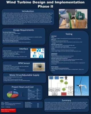
Project Goals • Generate a useable amount of electric power • Demonstrate turbine in a visible location on campus • Evaluate Union College’s potential for wind power generation Design and manufacture a micro-wind turbine to generate electricity for an on-campus application
Wind Speeds at Union Wind speeds are not desirable for wind power generation Most wind speeds occur at 1 mph Most high speeds occur at 3 mph High gusts up to 56 mph -% of the time speed is at 5 mph
Wind Speeds at Union • Summer season is least desirable • Winter Season better for wind turbine performance Shows seasonal fluctuations in wind speeds
Wind Tunnel Testing Needed 2nd Generation Models Successfully completed rotations Clocking Issues Final design based off 2nd gen models Too much resistance with torque setup
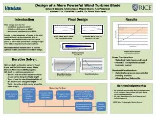
Hybrid VAWT SavoniusWind Turbines Self Starting Uses drag forces Lower efficiency Darriues Wind Turbines Not self-starting Uses drag and lift forces Highest VAWT Efficiency
Gear Ratio Expect approximately 100 RPMs from wind turbine • Timing Belt • Cheaper • Easier to switch outLess noise than chains • Beveled gear set • Expensive • Not easy to switch out • Chain and sprocket • Cheaper • Easy to switch out sprocket sizes • V Belt • Cheaper • Easier to switch out • Less noise than chains • Less resistance
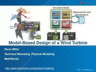
Electrical System DC-DC Converter BatteryBank Load Rectifier Inverter Alternator
Electrical System DC-DC Converter BatteryBank Load Rectifier Inverter Alternator
Electrical System DC-DC Converter BatteryBank Load Rectifier Inverter Alternator • Design Goals • Safely charge battery • Broaden range of usable wind speeds • Maximize system efficiency • Synchronized data acquisition
Electrical System DC-DC Converter BatteryBank Load Rectifier Inverter Alternator • Design Goals • Safely charge battery • Broaden range of usable wind speeds • Maximize system efficiency • Synchronized data acquisition
Generator Selection • Design Considerations • Generators vs. Alternators • Starting Torque • Direct-Drive vs. Gear-Drive • Power Curves • Conclusions • Alternators can produce three phase AC • More efficient • Allows for control over rectification • Low starting torque was critical • Single step gear • Unavoidable given project magnitude and region’s average wind speeds • Needed higher voltages at lower speeds Source: Gin Long Permanent Magnet Generators Site: http://www.ginlong.com
Generator Selection • Decision • WindBlueDC-540 • Three phase AC • Rewound stator provides higher voltages at lower RPMs • 12 V at 150 RPM • Low starting torque Source: Wind Blue Power Site: http://www.windbluepower.com/
Alternator Testing • DC motor used to drive alternator • Required heavy-duty power source • Power in, torque, RPM, and power out data collected • Used to create current, voltage, and efficiency curves
Rectification • Design Considerations • Three-phase AC output from alternator • Heat dissipation • Decision • Three-phase full-wave bridge rectifier • Large heat sink can easily dissipate expected power levels Source: Wind Blue Power Site: http://www.windbluepower.com/ Source: Lessons in Electronic Circuits Site: http://www.ibiblio.org/kuphaldt/electricCircuits/Semi/03269.png
DC-DC Converter • Design Considerations • Wind speed is not constant • Alternator will output varying amounts of power • Union’s average wind speeds are low but not always • Battery bank requires different current ratings • Depends upon depth of discharge • Consistent overcharging of battery bank leads to premature failure • Charging voltage needs to stay within .7 V of the nominal battery voltage • Voltage regulation is critical
DC-DC Converter • Options • Linear voltage regulator • Simpler design • Input must be at least 3 V above output voltage • Low efficiency • Switch-mode power converter • Various topologies for outputs above or below inputs • High efficient • More complex • Decision • Buck/Boost switch-mode converter • Raises or lowers input voltage to obtain desired output • Controlled by altering switch duty cycle
DC-DC Converter Basic Topology Vin Vout where D is duty cycle On State Off State Vin Vout Vin Vout
DC-DC Converter Continuous Conduction Mode vs. Discontinuous Conduction Mode Source: Wiki Commons Site: http://en.wikipedia.org/wiki/Buck%E2%80%93boost_converter
DC-DC Converter • Goals • Operate in continuous conduction mode • Maintain a low output voltage ripple • Effectively regulate voltages between 9-15V to a nominal 12.5V Design Where fs is the switching frequency IL is the inductor current ripple VC is the capacitor voltage ripple MultiSim buck/boost schematic
Implementation • Switching frequency is limited by BASIC STAMP 2px PWMPAL coprocessor • Duty cycle is controllable only up to 2kHz • Inductor series resistance is a serious limiting factor • Trouble driving power MOSFET • Transistor capacitance slows turn-off time, limiting effective duty cycle • Driver ICs may increase performance • NS754410, used as a voltage-controlled switch, also exhibits slow shut off time • Current implementation only allows for output voltage adjustment up to +/-while still operating in continuous conduction mode
Battery Selection • Design Considerations • Charging safety • Batteries may be thoroughly discharged over lifecycle • Temperature • Decision • 37Ah Sealed AGM battery • Robust to deep discharging • Superior cold weather performance • Cheaper than gel cell battery with comparable performance Source: MK Battery Site: http://www.mkbattery.com/
Inverter Selection • Design Considerations • Will determine power output quality • Sine Wave vs. Modified Sine Wave vs. Square Wave • 12v DC input, 120V 60Hz output • Decision • AIMS 300W pure sine wave inverter • Cost was comparable to modified sine wave inverter • Will allow for more diverse loads • 90% efficient Source: AIMS Power Site: http://www.aimscorp.net/
Load Selection • Design Considerations • Contribute to campus in some way • Promote sustainability at Union • Relatively low power consumption • Decision • Programmable LED sign • Draws 1A at 120V 60Hz
Datalogging Design Requirements • Synchronized sensing of wind speed, turbine RPMs, and charging voltage • External storage for ease of use and large amounts of data • Microcontroller-based Implementation with the BASIC Stamp 2px • NRG #40 anemometer outputs a frequency proportional to wind speed • Tested in wind tunnel, • Accurate within 1 MPH • Hall effect transistor used to sense turbine rotations • Successfully implemented in tested against strobe tachometer • Results were comparable • Voltage sensing capability through operational amplifier circuit and A/D converter • Memory-stick datalogger successfully records data into a text file for importation into Excel Source: Parallax Site: http://www.Parallax.com
Continuing Development • Buck/boost converter implementation • Investigating better switch drivers • Inductors with lower series resistance • Integration with final micro-turbine prototype • Demonstration on campus
References • Kassakian, John. Principles of Power Electronics. Reading, MA: Addison-Wesley, 1991 • Ang, Simon. Power Switching-Converters. New York: Marcel Dekker, 1995 • Lessons in Electronic Circuits, http://www.ibiblio.org/kuphaldt/electricCircuits/Semi/03269.png • WindBlue Power, http://www.windbluepower.com/ • Source: Wiki Commons, http://en.wikipedia.org/wiki/Buck%E2%80%93boost_converter • MK Battery, http://www.mkbattery.com/ • Gin Long Permanent Magnet Generators, http://www.ginlong.com • AIMS Power, http://www.aimscorp.net/ • Parallax, http://www.Parallax.com