Download

1 / 21
210 likes | 363 Vues
OPTIONS FOR THE DESIGN OF A NEW PICK-UP AND SCHEDULE. G. Kotzian, LIU-SPS High Bandwidth Damper Review, July 30, 2013. HBTFB - High Bandwidth Transverse Feedback. Wideband feedback system (GHz bandwidth) Intra-bunch GHz transverse feedback system

E N D
OPTIONS FORTHE DESIGN OF A NEW PICK-UPAND SCHEDULE G. Kotzian, LIU-SPS High Bandwidth Damper Review, July 30, 2013
HBTFB - High Bandwidth Transverse Feedback • Widebandfeedback system (GHz bandwidth) • Intra-bunch GHz transverse feedback system • Help stabilize beamagainst Ecloud and TMCI effects • Under development with LARP supported by: US-LARP CERN SPS LIU Project Kicker BPM Beam Active closed loop GHz Feedback Analog Back End Analog Front End Signal Processing DAC ADC Power Amp sampled position “slices” calculated correction data correction signal transverse position pre-distortion drive signal pre-processed
OVERVIEW • Design Considerations • Strip-line Pick-up Options • Coupler type pick-ups • Current PU: Exponential coupler BPW(A) • Strip-line BPCL • Long Strip-line Option • Variation of strip-line for scrubbing beam optimization • Alternative PUs • Electromagnetic PU: Position Sensitive Wall Current Monitor • Exotic (i.e. electro-optic) PUs • Faltin-type (not treated today) • Schedule • On-going activities • Possible Roadmap
Design considerations • Option to split system into several bands to cover entire frequency range • Centre frequenciesof instabilities moving during acceleration • Adequate adjustment of loop delay and for all bands (5 degphase@1GHz approx. ~14 ps) • Overlap of bands becomes delicate • Option for direct digitization with high bandwidth ADCs (GSPS) • Direct representation of beam transverse motion • Gain and phase equalization realizable using digitally implemented filters • Loop delay adjustment follows acceleration • Analog BW: 10 MHz – 2 GHz • Lower end covered by classical damper(dipole mode, large injection oscillations require strong damping) • Upper limit defined by Nyquistfrequency for subsequent sampling (fs > 4 GSPS) • SPS 200 MHz RF System: 5ns bucket length • With 4 GSPS 20 slices/bucket • NB: observed signal is always position x intensity holds information on longitudinal and transverse motion
Design considerations • SCOPE: PU design; requires taking into accountproperties of pre-processing chain (cables, filters, attenuators/amplifiers, orbit suppression signal processing) GOAL: provide analog representation of beam transverse position for direct digitization with high bandwidth ADC (few GSPS) Equalizer 7/8’’ transmission line BPM Passive Closed Orbit Suppression Delay adjustment ADC Equalizer 7/8’’ transmission line
Coupler type pick-ups logarithmic scale: dBMax(1V/m), 70 dB range Frequency Domain |ZT (w)| ^ ZT (w) = ZT j sin(wt/2) e -jwt/2 t ^ ZT … load or short Beam L … assuming w f=1/(2t) t = 2 L/c PU output voltage, matched in 50 Ω notches in freq. response direct representation of the bunch profile Use direct sampling and gating on single pulse: in time domain to effectively remove notch in frequency response:
Current PU: Exponential Stripline (BPWA) Developed for SPS by T. Linnecar, Reference: CERN-SPS-ARF-SPS/78/17 Special case: no notches in frequency response due to tapering of electrodes Four such couplers installed in SPS (four electrodes at 45 degrees) (Courtesy W. Höfle, SPS Studies WG - August 5, 2008) … but: phase response not linear with frequency !
Exponential PU – Beam response with coaxial transmission line w/o coaxial transmission line Gaussian bunch Reversed PU Ringing due to cable TF Ideal PU response PU response with dispersive and corrugated cable shows ringing in time domain
Bunchlet in BPWA 2 short bunches, 5ns spaced PU response w/o cables Reversed PU PU response with dispersive and corrugated cable (Courtesy W. Höfle) • Observation: • BWPA length of 375 mm was chosen to just separate two successive bunches • no mixing when bunches are split; however not so evident when closer • May need another iteration taking into account the implemented or an improved phase compensationK. Pollock, Signal Equalizer for SPS ECloud/TMCI Instability Feedback Control Systemhttp://ibic12.kek.jp/prepress/papers/tupa32.pdf
Exponential strip-line BPW (A/B) • Advantages • mechanically short L = 375 mm • no notches in frequency response due to tapering of electrodes • 4 electrodes, can be wired horizontally or vertically • Limitations • Vacuum chamber cut-off frequency for TE11 mode at 1.64 GHz (D=107mm, BPWA/BPWB) resp. 1.134 GHz (D=155mm, BPW) • phase response not linear, thus group delay frequency dependent; need to compensate for PU response and cable dispersion • impedance variation & matching was difficult to control in the design (T. Linnecar) production of matching not perfect • 1 of the 4 existing devices may be damaged, will be inspected during LS1 • For MDs and demonstrator system OK; fully functional system: what are better options?
Strip-line BPCL • Existing device: SPS BPCL • L = 600 mm, two planes • 50 Ω downstream termination • Flat response up to ~3 GHz • SPS head-tail application: • Performs a 2-dim Wiener de-convolution • re-aligns the initial signal and successive reflection • Advantages: • Existing devices • possible for bunch lengths up to max. 4ns • Limitations: • 600 mm electrode length not sufficient for max. bunch length of 5ns ( • higher order cut-off frequency in PU body fc=1.32 GHz (problematic? possible damping with ferrites?) • R. Steinhagen Courtesy: R. Steinhagen Courtesy: R. Steinhagen
Long strip-line Option • Optimal solution: separate positive and negative output pulses • Required minimum length • Reserved location: 319.31 (existing BPWA to 311.01 during LS1) • Available length: 1426 mm (see H. Bartosik) • Assuming a beam tube inner radius of (: • TE11 cut-off frequency • The stay-clear half-aperture for the pick-up is . • For an electrode thickness of • height of strip-line gap • For a strip-line design • strip-line width • Find trade-off between TE11 cut-off (i.e. ) and expected signal level () • Strip-line with this length probably needs intermediate supports. Details are subject to future studies. stay-clear aperture limit BPWA BPCL calculations based on: J-P. Papis, L. Vos, CERN SL/91-g (BI)
Long strip-line – Option II • Due to pattern of the bunchlet beam (bunch spacing is here 5ns!): • signal of the second bunch will overlap with residual pulse (if ) • In order to resolve doublet scrubbing beam requires strip-line with delay • Required minimum length • Too long for 319.31 (1426 mm), needs also 319.32 to be freed up (current plan for LS2: BPWA 319.01 319.32) • If full length available, i.e. 2286 mm leaves comfortable margin for PU, flanges, bellows, etc. • Constraints for coupler-type PUs: • The strip-line length must be longer than the bunch lengthin order to have no overlap between the bipolar pulses for 5ns bunches for 10ns doublets • Gap between successive bunches (or bunchlets) necessary, otherwise cancelation of beam signal with residual reflection gap length ≥ strip-line delay • Remark: if PU length not sufficient for bunchlet beam then one could think of using the negative pulse of the second bunch which – in the ideal case – is unperturbed and with a negative gate (time alignment of pulse w.r.t. to first bunch required).
Variation of strip-line for scrubbing beam optimization • Challenge in direct representation of bunch profiles using coupler-type PUs: the residual reflection spoils the response. • exponential coupler uses tapered electrodes • long strip-line with delayed reflection • Quest: Absorb the residual reflection in bulk material • Studies on-going … localized load material with adjusted bulk conductivity
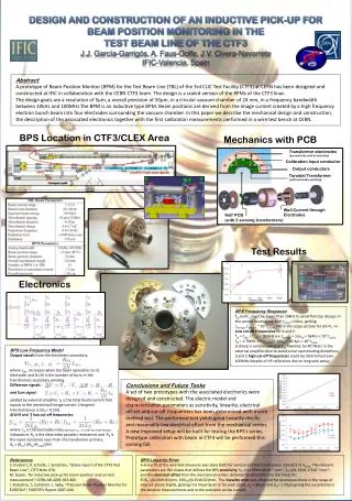
Position Sensitive Wall-Current Monitor Option • BPM based on M. Gasior design • AB-Note-2003-082-BDI: A proposal for an Inductive Pick-Up for Measuring the Position and Current of Proton Beams in the Transfer Lines between the Linac 2 and the PSB • adapted from and based on an inductive pick-up (IPU),developed for position and current measurement in CTF3 • Bandwidth starting from 100 kHz up >1 GHz should be feasible • 1-10 Ohm loading, differential L~70 nH taken from: M. Gasior, AB-Note-2003-082-BDI Scale this version to fit to the SPS vacuum chamber 100 kHz 1 GHz Provided by R. Steinhagen
EO-PBM – Electro-Optical Pick-Up • Working principle similar to LCD/TFT screen: particle beam modulates crystal birefringence (double refracting) → intensity of two laser beams A & B, position ~ (A-B)/(A+B) • Pro: very wide-band signal, no beam power issues, true DC response (alt. AGM?) • Only lab tests for the full assembly until now • Hope to have a in-vacuum prototype ready for post-LS1 → to be published (Courtesy R. Steinhagen) SPS-ECA4 SPS-LSS4.421 532/1550 nm Laser MM or SM (not matched) locally stabilised ΔT< 0.1-1°C P A OM4 (matched) p-beam x2 P A EO-Hybrid Analog FE DAQ: Scope & Multiband-Inst._Mon. Σ & Δ tunnel (Courtesy R. Steinhagen)
On-going activities • Pick-up design • 3D-EM simulations and documentation of long strip-line design • Verification using HFSS and CST Microwave/Particle Studio • Evaluation of “terminated” strip-line performance (also thermal simulation including losses) • Optimization for length reduction/tapering of electrodes • Closed Orbit Suppression • suppression of common mode signal to avoid amplifier saturation and good usage of dynamic range (digitization) • Fact-finding: programmable step attenuators with required resolution 0.1 dB/step • Preparation of hardware & firmware development (for use with VME form factor) • Coaxial transmission lines • New smooth-wall coaxial transmission lines installed during LS1(lower dispersion than corrugated cables) • Characterisation measurement method utilizes “synthetic TDR” via commercial VNAs (high sensitivity) • Equalize cable length (equal pairs of same length for pick-up A and B outputs)
Possible Roadmap • New Pick-up design • Finalize EM-design until end 2013 + down selection which PU to be realized • Produce design drawings in 2014-2015 • Prototyping and lab testing 2015-2016,to be ready for installation at the latest in LS2 • Closed orbit suppression • Start HW development after fall 2013 • Possiblesynergies with other active projects, e.g. damper HW upgrade project • Finalize HW and firmware in 2014 • Ready for tests with beam in the SPS after LS1 • Coaxial transmission lines • May require new analog compensation filters • Adapt analog front-end for optimum signal levels to fast ADCs
Button electrodes - Variant of electrostatic electrodes • taken from: Robert E. Shafer, BEAM POSITION MONITORING • Button electrode response to a single Gaussian beam bunch: bipolar doublet, occurs at about