Download
1 / 30
1.21k likes | 6.52k Vues
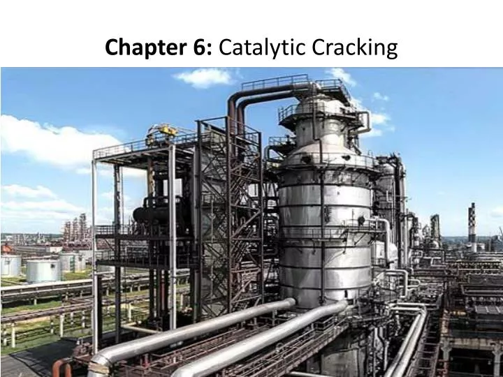
Chapter 6: Catalytic Cracking. Catalytic cracking is the most important and widely used refinery process for converting heavy oils into more valuable gasoline and lighter products

E N D
Catalytic cracking is the most important and widely used refinery process for converting heavy oils into more valuable gasoline and lighter products • Originally cracking was accomplished thermally but the catalytic process has almost completely replaced thermal cracking because more gasoline having a higher octane and less heavy fuel oils and light gases are produced. • The light gases produced by catalytic cracking contain more olefins than those produced by thermal cracking (Table 6.1).
The cracking process produces carbon (coke) which remains on the catalyst particle and rapidly lowers its activity. • To maintain the catalyst activity at a useful level, it is necessary to regenerate the catalyst by burning off this coke with air. • As a result, the catalyst is continuously moved from reactor to regenerator and back to reactor. • The cracking reaction is endothermic and the regeneration reaction exothermic. • Some units are designed to use the regeneration heat to supply that needed for the reaction and to heat the feed up to reaction temperature. These are known as ‘‘heat balance’’ units.
Average riser reactor temperatures are in the range 900 to 1000°F (480– 540°C), with oil feed temperatures from 500 to 800°F (260–425°C) and regenera- tor exit temperatures for catalyst from 1200 to 1500°F (650–815°C). • The catalytic-cracking processes in use today can all be classified as either moving-bed or fluidized-bed units. • There are several modifications under each of the classes depending upon the designer or builder, but within a class the basic operation is very similar. • The Thermafor catalytic cracking process (TCC) is representative of the moving-bed units and the fluid catalytic cracker (FCC) of the fluidized-bed units
The process flows of both types of processes are similar. • The hot oil feed is contacted with the catalyst in either the feed riser line or the reactor. • As the cracking reaction progresses, the catalyst is progressively deactivated by the formation of coke on the surface of the catalyst. • The catalyst and hydrocarbon vapors are separated mechanically, and oil remaining on the catalyst is removed by steam stripping before the catalyst enters the regenerator. • The oil vapors are taken over head to a fractionation tower for separation into streams having the desired boiling ranges.
The spent catalyst flows into the regenerator and is reactivated by burning off the coke deposits with air. • Regenerator temperatures are carefully controlled to prevent catalyst deactivation by overheating and to provide the desired amount of carbon burn-off. This is done by controlling the air flow to give a desired CO/CO ratio in the exit flue gases or the desired temperature in the regenerator. • The flue gas and catalyst are separated by cyclone separators and electrostatic precipitators. • The catalyst in some units is steam-stripped as it leaves the regenerator to remove adsorbed oxygen before the catalyst is contacted with the oil feed
CRACKING REACTIONS The products formed in catalytic cracking are the result of both primary and secondary reactions Primary reactions are designed as those involving the initial carbon–carbon bond scission and the immediate neutralization of the carbonium ion
CRACKING OF PARAFFINS • The catalytic cracking of paraffins is characterized by high production of C3and C4 • Hydrocarbons in the cracked gases, reaction rates and products determined by size and structure of paraffins • Isomerization to branched structures and aromatic hydrocarbons formation resulting from secondary reactions involving olefins
OLEFIN CRACKING • The catalytic cracking rates of olefinic hydrocarbons are much higher than those of the corresponding paraffins. • The main reactions are : • Carbon–carbon bond scissions • Isomerization • Polymerization • Saturation, aromatization, and carbon formation • Olefinisomerization followed by saturation and aromatization are responsi- ble for the high octane number and lead susceptibility of catalytically cracked gasolines.
CRACKING OF NAPHTHENIC HYDROCARBONS • The most important cracking reaction of naphthenes in the presence of silica- alumina is dehydrogenation to aromatics. • There is also carbon–carbon bond scission in both the ring and attached side chains but at temperatures below 1000°F (540°C) the dehydrogenation reaction is considerably greater. • Dehydrogenation is very extensive for C9 and larger naphthenes and a high-octane gasoline results. • The non-ring liquid products and cracked gases resulting from naphthenic hydrocarbon cracking are more saturated than those resulting from cracking paraffins.
AROMATIC HYDROCARBON CRACKING • Aromatic hydrocarbons with alkyl groups containing less than three carbon atoms are not very reactive. • The predominant reaction for aromatics with long alkyl chains is the clean splitting off of side chains without breaking the ring. • The carbon–carbon bond ruptured is that adjacent to the ring, and benzene compounds containing alkyl groups can be cracked with nearly quantitative recovery of benzene
CRACKING CATALYSTS • Commercial cracking catalysts can be divided into three classes: • acid-treated natural aluminosilicates • amorphous synthetic silica-alumina combinations • crystalline synthetic silica-alumina catalysts called zeolites or molecular sieves • Most catalysts used in commercial units today are either class 3 or mixtures of classes 2 and 3 catalysts
The advantages of the zeolite catalysts over the natural and synthetic amorphous catalysts are: • Higher activity • Higher gasoline yields at a given conversion 3. Production of gasolines containing a larger percentage of paraffinic and aromatic hydrocarbons 4. Lower coke yield (and therefore usually a larger throughput at a given conversion level) 5. Increased isobutane production 6. Ability to go to higher conversions per pass without overcracking
The catalytic effects of zeolitic catalysts can be achieved with only 10 to 25% of the circulating catalyst as zeolites and the remainder amorphous silica-alumina cracking catalyst. • Amorphous catalysts have higher attrition resistance and are less costly than zeolitic catalysts. • Most commercial catalysts contain approximately 15% zeolites and thus obtain the benefits of the higher activity and gasoline selectivity of the zeolites and the lower costs and make-up rates of the amorphous catalysts. • Lower attrition rates also greatly improve particulate emission rates. • Basic nitrogen compounds, iron, nickel, vanadium, and copper in the oil act as poisons to cracking catalysts
FCC FEED PRETREATING • The trend toward low sulfur and nitrogen contents in gasolines and diesel fuels requires that either the FCC unit feed or products be treated to reduce sulfur and nitrogen. • Treating feed to the FCC unit offers the advantages that the sulfur and nitrogen in the gasoline and diesel fuel products are reduced and, by adding hydrogen to the feed, naphtha and LCO yields are increased without lowering the olefins content and octanes of the naphtha fraction. • For refineries that do not hydrotreat the FCC feed or naphtha products, over 95% of the sulfur in the gasoline blending pool is from the FCC naphtha.
The hydrotreating unit can be operated in several ways: as a • hydrodesulfurization (HDS) unit, • a mild hydrocracking (MHC) unit, or • a partial-conversion hydrocracking unit. • In all cases the product sulfur content has to be less than 135 wppm to produce a refinery gasoline blending pool with less than 50 wppm sulfur and less than 85 wppm to produce a refinery gasoline blending pool of less than 30 wppm
PROCESS VARIABLES • In addition to the nature of the charge stock, the major operating variables effecting the conversion and product distribution are the cracking temperature, catalyst/oil ratio, space velocity, catalyst type and activity, and recycle ratio. • Activity: Ability to crack a gas oil to lower boiling fractions. • Catalyst/oil ratio (C/O) = lb catalyst/lb feed. • Conversion = 100 × (volume of feed - volume of cycle stock)/volume of feed. • Cycle stock: Portion of catalytic-cracker effluent not converted to naphtha and lighter products [generally the material boiling above 430°F (220°C)] • Efficiency = (% gasoline) × conversion. • Recycle ratio = Volume recycle/volume fresh feed. • Selectivity: The ratio of the yield of desirable products to the yield of undesirable products (coke and gas).
Space velocity: Space velocity may be defined on either a volume (LHSV) or a weight (WHSV) basis. • In a fluidized-bed reactor, the LHSV has little meaning because it is difficult to establish the volume of the bed. The weight of the catalyst in the reactor can be easily determined or calculated from the residence time and C/O ratio. • LHSV = Liquid hour space velocity in volume feed/(volume catalyst) (hr). • WHSV = (Weight hour space velocity in lb feed)/(lb catalyst) (hr). If t is the catalyst residence time in hours, then • WHSV = 1/(t)(C/O).
Within the limits of normal operations, increasing 1. Reaction temperature 2. Catalyst/oil ratio 3. Catalyst activity 4. Contact time • results in an increase in conversion, while a decrease in space velocity increases conversion. • It should be noted that an increase in conversion does not necessarily mean an increase in gasoline yield • An increase in temperature above a certain level can increase conversion, coke and gas yields, and octane number of the gasoline but decrease gasoline yield
In fluidized-bed units, the reactor pressure is generally limited to 15 to 20 psig by the design of the unit and is therefore not widely used as an operating variable. • Increasing pressure increases coke yield and the degree of saturation of the gasoline but decreases the gasoline octane. It has little effect on the conversion. • The initial catalyst charge to a FCC unit using riser cracking is about 3 to 5 tons of catalyst per 1000 BPSD charge rate. • Catalyst circulation rate is approxi- mately 1 ton/min per MBPD charge rate.
HEAT RECOVERY • The hot gases are at high temperature [1100 to 1250°F (595–675°C in the former case and 1250 to 1500°F (675–815°C) in the latter] and at pressures of 15 to 25 psig (103–172 kPa). • Many catalytic crackers include waste heat boilers which recover the sensible heat by steam generation and others use power recovery turbines to generate electric power or compress the air used in the catalytic cracker regenerator. • Some refineries recover the heat of combustion of the carbon monoxide in the flue gas by installing CO-burning waste heat boilers in place of those utilizing only the sensible heat of the gases. • An even higher rate of energy recovery can be achieved by using a power recovery turbine prior to the CO or waste heat boiler, although when regenerator pressures are less than 15 psig, power recovery turbines usually are not economic.
Assuming a regenerator flue gas discharge pressure of 20 psig (138 kPa) and 1000°F (538°C), the available horsepower per pound per second of gas flow for the various schemes are