Download
1 / 18
180 likes | 279 Vues
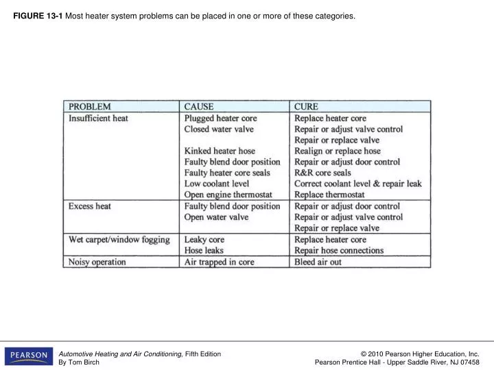
FIGURE 13-1 Most heater system problems can be placed in one or more of these categories. FIGURE 13-2 Heater output, measured at the floor outlet, should be at or above the temperatures shown.

E N D
FIGURE 13-1 Most heater system problems can be placed in one or more of these categories.
FIGURE 13-2 Heater output, measured at the floor outlet, should be at or above the temperatures shown.
FIGURE 13-3 Heater hose temperature can be checked quickly with an infrared thermometer. This return hose is 189°F, which indicates good flow through the heater core.
FIGURE 13-4 A special tool (a and b) is required to release the lock on quick-connect heater hose couplers. The O-rings (c) must be in good condition and lubricated with silicone to prevent leaks. (Courtesy of Four Seasons)
FIGURE 13-5 An alternate repair method for damaged heater hoses using quick-connect couplers is to cut off the ferrule (a), remove the damaged hose from the quick-connect nipple (b), and clamp a new hose onto the nipple (c). (Courtesy of The Gates Rubber Company)
FIGURE 13-6 One heater core connector is plugged as the vacuum tester pumps the core into a vacuum to test for leaks. A pressure tester can also be used in the same way. (Courtesy of Stant Manufacturing)
FIGURE 13-7 Some heater cores can be removed and replaced with the case still mounted (a and b). Many require that the assembly be removed; then the core is removed from the assembly and replaced (c). (a, b. Courtesy of Saturn Corporation; c. Courtesy of Chrysler LLC)
FIGURE 13-8 In many systems, the heater core or its hoses are above the engine’s water jackets. Loosening the upper heater hose allows the air lock to leave and coolant to enter the core.
FIGURE 13-9 This manufacturer recommends filling this rearmounted heater core with coolant before installing it in the vehicle.( Courtesy of Chrysler LLC)
FIGURE 13-10 This cabin/clean-air filter is replaced by lowering the glove box door and removing a cover panel. (Provided courtesy of Toyota Motor Sales USA, Inc.)
FIGURE 13-11 A slightly dirty filter is being removed from the freshair chamber (a) (under hood), and a new filter is being slid into the opening (b).
FIGURE 13-12 After removing the fascia panel and two retaining screws, this control head was pulled outward to gain access to the mechanical, electrical, and vacuum connections.
FIGURE 13-13 This system uses a function control cable to operate the two mode doors and a temperature cable to operate the temperature-blend door.
FIGURE 13-14 A small gap (arrow) should be between the temperature lever (full cold position) and the end of its slot if the cable is adjusted properly.
FIGURE 13-15 Most of the components of this vacuum control circuit are under the instrument panel.
FIGURE 13-16 This diagram shows the vacuum circuit during the recirculating-panel-control-head vacuum switch position. (Courtesy of Chrysler LLC)
FIGURE 13-17 Vacuum leaks can be located using a hand vacuum pump and gauge while isolating portions of the circuit using plugs or pliers.
FIGURE 13-18 Sometimes a vacuum leak can be located by listening for a “hiss” with the aid of a small hose.