Download
1 / 29
290 likes | 573 Vues
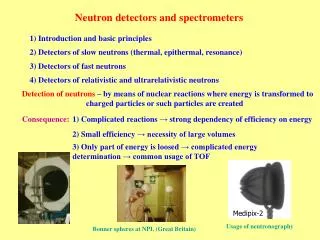
Neutron Detectors for Materials Research. T.E. Mason Associate Laboratory Director Spallation Neutron Source Acknowledgements: Kent Crawford & Ron Cooper. Neutron Detectors. What does it mean to “detect” a neutron?

E N D
Neutron Detectors for Materials Research T.E. Mason Associate Laboratory Director Spallation Neutron Source Acknowledgements: Kent Crawford & Ron Cooper
Neutron Detectors • What does it mean to “detect” a neutron? • Need to produce some sort of measurable quantitative (countable) electrical signal • Can’t directly “detect” slow neutrons • Need to use nuclear reactions to “convert” neutrons into charged particles • Then we can use one of the many types of charged particle detectors • Gas proportional counters and ionization chambers • Scintillation detectors • Semiconductor detectors
Nuclear Reactions for Neutron Detectors • n + 3He 3H + 1H + 0.764 MeV • n + 6Li 4He + 3H + 4.79 MeV • n + 10B 7Li* + 4He7Li + 4He + 0.48 MeV +2.3 MeV (93%)7Li + 4He +2.8 MeV ( 7%) • n + 155Gd Gd* -ray spectrum conversion electron spectrum • n + 157Gd Gd* -ray spectrum conversion electron spectrum • n + 235U fission fragments + ~160 MeV • n + 239Pu fission fragments + ~160 MeV
Gas Detectors ~25,000 ions and electrons produced per neutron (~410-15 coulomb)
Gas Detectors – cont’d • Ionization Mode • electrons drift to anode, producing a charge pulse • Proportional Mode • if voltage is high enough, electron collisions ionize gas atoms producing even more electrons • gas amplification • gas gains of up to a few thousand are possible
Material Density of 6Li atoms (cm-3) Scintillation efficiency Photon wavelength (nm) Photons per neutron Some Common Scintillators for Neutron Detectors 0.45 % 395 nm ~7,000 Li glass (Ce) 1.751022 2.8 % 470 ~51,000 LiI (Eu) 1.831022 9.2 % ~160,000 ZnS (Ag) - LiF 1.181022 450
Anger camera • Prototype scintillator-based area-position-sensitive neutron detector • Designed to allow easy expansion into a 7x7 photomultiplier array with a 15x15 cm2 active scintillator area. • Resolution is expected to be ~1.5x1.5 mm2 2000-03449/arb
Semiconductor Detectors cont’d • ~1,500,000 holes and electrons produced per neutron (~2.410-13 coulomb) • This can be detected directly without further amplification • But . . . standard device semiconductors do not contain enough neutron-absorbing nuclei to give reasonable neutron detection efficiency • put neutron absorber on surface of semiconductor? • develop boron phosphide semiconductor devices?
Coating with Neutron Absorber • Layer must be thin (a few microns) for charged particles to reach detector • detection efficiency is low • Most of the deposited energy doesn’t reach detector • poor pulse height discrimination
Detection Efficiency • Full expression: • Approximate expression for low efficiency: • Where: • s = absorption cross-section • N = number density of absorber • t = thickness • N = 2.71019 cm-3 atm-1 for a gas • For 1-cm thick 3He at 1 atm and 1.8 Å, • = 0.13
Pulse Height Discrimination cont’d • Can set discriminator levels to reject undesired events (fast neutrons, gammas, electronic noise) • Pulse-height discrimination can make a large improvement in background • Discrimination capabilities are an important criterion in the choice of detectors ( 3He gas detectors are very good)
Position Encoding • Discrete - One electrode per position • Discrete detectors • Multi-wire proportional counters(MWPC) • Fiber-optic encoded scintillators (e.g. GEM detectors) • Weighted Network (e.g. MAPS LPSDs) • Rise-time encoding • Charge-division encoding • Anger camera • Integrating • Photographic film • TV • CCD
Multi-Wire Proportional Counter • Array of discrete detectors • Remove walls to get multi-wire counter
MWPC cont’d • Segment the cathode to get x-y position
Resistive Encoding of a Multi-wire Detector • Instead of reading every cathode strip individually, the strips can be resistively coupled (cheaper & slower) • Position of the event can be determined from the fraction of the charge reaching each end of the resistive network (charge-division encoding) • Used on the GLAD and SAND linear PSDs
Resistive Encoding of a Multi-wire Detector cont’d • Position of the event can also be determined from the relative time of arrival of the pulse at the two ends of the resistive network (rise-time encoding) • Used on the POSY1, POSY2, SAD, and SAND PSDs • There is a pressurized gas mixture around the electrodes
Anger camera detector on SCD • Photomultiplier outputs are resistively encoded to give x and y coordinates • Entire assembly is in a light-tight box
Micro-Strip Gas Counter • Electrodes printed lithgraphically • Small features – high spacial resolution, high field gradients – charge localization and fast recovery
Crossed-Fiber Scintillation Detector Design Parameters (ORNL I&C) • Size: 25-cm x 25-cm • Thickness: 2-mm • Number of fibers: 48 for each axis • Multi-anode photomultiplier tube: Phillips XP1704 • Coincidence tube: Hamamastu 1924 • Resolution: < 5-mm • Shaping time: 300 nsec • Count rate capability: ~ 1 MHz • Time-of-Flight Resolution: 1 msec
Neutron Detector Screen Design The scintillator screen for this 2-D detector consists of a mixture of 6LiF and silver-activated ZnS powder in an epoxy binder. Neutrons incident on the screen react with the 6Li to produce a triton and an alpha particle. Collisions with these charged particles cause the ZnS(Ag) to scintillate at a wavelength of approximately 450 nm. The 450 nm photons are absorbed in the wavelength-shifting fibers where they converted to 520 nm photons emitted in modes that propagate out the ends of the fibers. The optimum mass ratio of 6LiF:ZnS(Ag) was determined to be 1:3. The screen is made by mixing the powders with uncured epoxy and pouring the mix into a mold. The powder then settles to the bottom of the mold before the binder cures. After curing the clear epoxy above the settled powder mix is removed by machining. A mixture containing 40 mg/cm2 of 6LiF and 120 mg/cm2 of ZnS(Ag) is used in this screen design. This mixture has a measured neutron conversion efficiency of over 90%.
16-element WAND Prototype Schematic and Results Clear Fiber 2-D tube Coincidence tube Neutron Beam Wavelength-shifting fiber Aluminum wire Scintillator Screen
Principle of Crossed-Fiber Position-Sensitive Scintillation Detector Outputs to multi-anode photomultiplier tube 1-mm Square Wavelength-shifting fibers Scintillator screen Outputs to coincidence single-anode photomultiplier tube
Neutron Scattering from Germanium Crystal Using Crossed-fiber Detector • Normalized scattering from 1-cm high germanium crystal • En ~ 0.056 eV • Detector 50-cm from crystal
All fibers installed and connected to multi-anode photomultiplier mount