Download
1 / 42

E N D
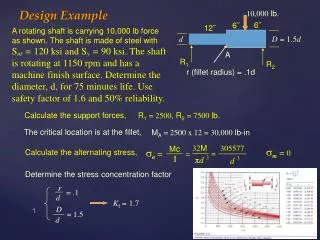
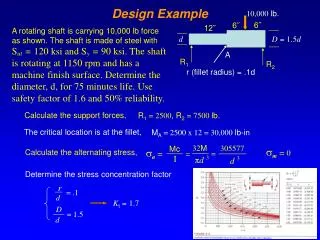
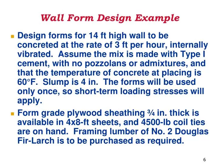
Wall Form Design Example • Design forms for 14 ft high wall to be concreted at the rate of 3 ft per hour, internally vibrated. Assume the mix is made with Type I cement, with no pozzolans or admixtures, and that the temperature of concrete at placing is 60°F. Slump is 4 in. The forms will be used only once, so short-term loading stresses will apply. • Form grade plywood sheathing ¾ in. thick is available in 4x8-ft sheets, and 4500-lb coil ties are on hand. Framing lumber of No. 2 Douglas Fir-Larch is to be purchased as required.
Wall Form Design Example • STEP 1: FIND PRESSURE. • The concrete used for this project satisfied the conditions of Table 5-4. • Using Table 5-5B, for R = 3 ft/hr, and T = 60F, the minimum pressure for design is: P = 600 psf • Then the depth of the hydrostatic load zone, for a concrete with a unit weight of 150 pcf is:
Wall Form Design Example • The diagram of lateral pressure on wall form is shown here:
Wall Form Design Example • STEP 2: SHEATHING. • 4x8 sheets of plywood will be used. Use plywood the "strong way" (face grain parallel to plywood span). Design for uniformly spaced supports at 1-ft center-to-center. • CHECK BENDING • Consider a 12-in. wide strip of plywood. • For continuous beams (more than three supports) the following equation is used:
Wall Form Design Example • From Table 4-2, the bending stress for plywood is 1545 psi. • The problem states that the forms will be used only once (single-use form), the bending stress must be multiplied by an adjustment factor of 1.25 for short term loading. Hence, the allowable stress:
Wall Form Design Example • From Table 4-3, the section modulus, S, for ¾-in. plywood is: 0.412 in.3 • w, loading of the beam for a 1-ft wide strip of plywood is
Wall Form Design Example • Substituting in the equation:
Wall Form Design Example • CHECK DEFLECTION: • Again considering a 12-in. width of plywood sheathing, check the maximum allowable deflection (D) of the sheathing for l/360 of the span and 1/16 in., whichever is less. • From Table 4-2, the values for modulus of elasticity for plywood can be found as E = 1,500,000 psi, and Table 4-3 renders the value for the moment of inertia for plies parallel to the span as I = 0.197 in.4. • For D = l/360: • For D = l/16”:
Wall Form Design Example • CHECK ROLLING SHEAR: • From Table 4-2, allowable Fv (rolling shear stress) can be found to be Fv = 57 psi, which should be multiplied by 1.25 for short-term loading. Therefore, the allowable rolling shear stress is: • From Table 4-3, the value of the rolling shear constant, Ib/Q, can be found as 6.762. • Use the equation for maximum shear for a continuous plyform and solve for L:
Wall Form Design Example • SPACING OF THE STUDS: • From the above calculations, the smallest value obtained for l is 12.61 in. (bending governs), meaning that the studs CANNOT be placed any further than 12.61 inches apart. • We are using 8-ft.-wide plywood sheets. The sheets should have stud support at the joints. Therefore an equal-spacing of studs at 12-inches satisfies all conditions. USE STUDS WITH SPACING OF 1-FT.
Wall Form Design Example • STEP 3: STUD SIZE and SPACING OF WALES (Wales support the studs)
Wall Form Design Example • Design for 2x4 S4S studs. Find the maximum span that can support a lateral pressure of 600 psf. • Equivalent uniform load, w, is the max. lateral pressure times the stud spacing. Hence: Studs can be considered as continuous beams subjected to uniform loading. Like the previous set of calculations, check for allowable span for bending, deflection, and shear.
Wall Form Design Example • CHECK BENDING • Assume using No. 2 Douglas Fir-Larch studs. From Table 4-2, the extreme fiber bending stress, Fb, is 900 psi. However, this value should be adjusted for size factor and load duration factor. • See factors on Table 6-2 page 6-5. Note that all wet service, temperature, stability, Flat use will default to one. Repetitive use cannot be used if we are using duration factor of 1.25.
Wall Form Design Example • The first adjustment factor is the short-term loading factor of 1.25. The second adjustment factor is the size factor obtained from Table 4-2B, which is 1.5. Therefore:
Wall Form Design Example • The values of section modulus, S, for 2x4 S4S No. 2 Douglas Fir-Larch can be obtained from Table 4-1B as 3.06 in.3.
Wall Form Design Example • The allowable stud span as a continuous beam is:
Wall Form Design Example • CHECK DEFLECTION • The allowable deflection is less than l/360 of the span and 1/8 in., whichever is less. • Using Table 4-2, the values for modulus of elasticity for 2x4 S4S No. 2 Douglas Fir-Larch is E = 1,600,000 psi, and in Table 4-1B the value for the moment of inertia for is: I = 5.36 in.4 • For D = l/360: • For D = 1/8”:
Wall Form Design Example • CHECK SHEAR • From Table 4-2, allowable Fv (rolling shear stress) can be found to be Fs = 180 psi, which should be multiplied by 1.25 for short-term loading. Therefore, the allowable shear stress is: • A 2x4 S4S has an actual b = 1 ½ in. and d = 3 ½ in., which is obtained from Table 4-1B. Use the equation for maximum shear for a continuous beam and solve for l:
Wall Form Design Example • SPACING OF THE WALES • From the stud spans calculated above, the shortest span is based on bending which is 32.1 inches. • This means the wales, which are the stud supports CANNOT be spaced more than 32.1 inches apart (this span can be increased near the top, since in the top 4 ft., the pressure decreases linearly from 600 psf to 0). • The top and bottom wales are often set about 1 ft from top and bottom of wall forms.
Wall Form Design Example • Place wales 12 inches from both top and bottom of the wall form. • Then, 14' 1' 1' = 12 ft. or 144 inches remains for spacing the other wales, which can be no more than 32.1 inches apart. • Set them at 30 in., except one span at 24 in. (smaller spans at the bottom). • We place the smaller span near the bottom of the form where theoretically a higher pressure could occur.
Wall Form Design Example 30” = 2’6”
Wall Form Design Example STEPS 4 & 5: TIE DESIGN, WALE SIZE and TIE SPACING • From the pressure diagram, the equivalent uniform load per lineal foot of wale is determined to be 1500 lb/lf. • The problem statement indicates that 4500-lb coil ties are available and will be used.
Wall Form Design Example STEPS 4 & 5: TIE DESIGN, WALE SIZE and TIE SPACING(Cont’d) • With the maximum load per lineal foot of wale being 1500 lbs, then the maximum tie spacing is:
Wall Form Design Example • CHECK BENDING(Cont’d) • Maximum bending moment for a uniformly loaded continuous beam (more than 3 supports) is: • The maximum moment of the member being designed is: • Therefore: • Or:
Wall Form Design Example • CHECK BENDING • F'b is the allowable stress in the extreme fiber and was calculated to be 1687 psi. The span, l, is 3 ft. or 36 inches, and w = 1500 lb/lf. • Therefore the required section modulus, S, can be calculated using the above equation:
Wall Form Design Example • In order to avoid drilling of timbers, they commonly use double-member wale. So the required section modulus of 9.6 in.3 is for two members. • Referring to Table 4-1B, double 2x4s will yield a section modulus of 2x3.06 or 6.12 in.3, which is less than 9.6 in.3, and therefore not acceptable. • Checking the next larger size, 3x4, will result in: S = 2x 5.10 = 10.20 in.3> 9.6 in.3, which satisfies the section modulus requirements. Use double 3x4 wales.
Wall Form Design Example • CHECK SHEAR • To check the horizontal shear for the double 3x4 wales, use the horizontal shear stress formula for a uniformly loaded continuous beam. (They are exactly the same formulas) or • From Table 4-1B, the value of bd for a 3x4 member can be obtained as: 8.75 in.2 ( or simply: 2.5” x 3.5”=8.75 in.2 ) • Therefore the stress in the double 3x4 members meets the requirements. (The value of the adjusted allowable shear stress of 225 psi was calculated before).
Wall Form Design Example • STEP 6: BEARING CHECK • Check: • 1) bearing of the studs on wales and • 2) bearing between the tie washer or tie holders and wales. • From Table 4-2, the value of compression Perpendicular to grain, Fc, for No. 2 Douglas Fir-Larch is 625 psi.
Wall Form Design Example From page 6-10, the multiplying factors for indicated lengths of bearing on small area plates and washers are shown below: 3.5” (1.13+1.09)/2 = 1.11
Wall Form Design Example • TIES: Assume a 3½ in.-square tie washer. • Then the bearing area is: (3½)2 ¾3½ = 12.25 2.63 = 9.63 in.2 • Since this is a short bearing length, Fcshould be multiplied by a factor of 1.11 (refer to page 13 for 3½ in. bearing length): • Adjusted Fc= 625 (1.11) = 694 psi
Wall Form Design Example • The actual bearing stress is then: < 694 psi O.K.
Wall Form Design Example • STUDS ON WALES: • The bearing area between 2x4 studs and double 3x4 wales can be calculated as: 2 x (1½”x2½”) = 2 x 3.75 = 7.5 in.2 • Load transfer to the wale = ½ the stud span above and below the wale x the lateral pressure x the stud spacing < 625 psi O.K.
Wall Form Design Example 4x8-ft 3/4” thick plywood sheathing 2x4 S4S No. 2 Douglas Fir-Larch studs 12-in. O.C. 4500-lb coil ties with 3-ft spacing Double 3x4 wales 3 1/2 in.-square tie washer
Wall Form Design ExampleBracing for Lateral Loads • Consider the necessary bracing for a wall form 14 ft. high, above grade, in an area where the local building code specifies a minimum 20 psf wind loading. • Table 5-7 indicated that 140 lb per lineal foot should be used for design of bracing, since the wind force prescribed by local code gives a value larger than the 100 lb/ft minimum established by ACI Committee 347.
Wall Form Design ExampleBracing for Lateral Loads • Strut Bracing • If wooden strut bracing is provided, strong enough to take either a tension or compression load, then single side bracing may be used. • Nailed connections at either end must be strong enough to transmit the tension load, and wales or other form members must be strong enough to transmit accumulated horizontal forces to the strut bracing.
Wall Form Design ExampleBracing for Lateral Loads • Strut Bracing • If wooden bracing is attached 1 or 2 feet below the top of the wall, the bracing must carry more than the 140 lb per ft load applied at the top.
Wall Form Design ExampleBracing for Lateral Loads • Strut Bracing • H’ the horizontal bracing force 2 feet from the top of the wall would have to be • (14’/12’)(140 lb/ft) = 163 lb per ft • in order to balance the 140 lb/lf design load applied at the top of the wall. • If end of the brace is put 8 feet from the wall, use the relationship between sides of the right triangle to find the the length of brace and load it must carry.
Wall Form Design ExampleBracing for Lateral Loads • Strut Bracing
Wall Form Design ExampleBracing for Lateral Loads • If struts are spaced every 8 feet along the wall, then 8x294 = 2352lb must be carried by each brace. • Many wood members strong enough to carry this load in compression will also be adequate in tension. However, the strength of connections (nails, etc.) must be made adequate for the tension load.
Credits • Prof. Nemati originally made this PowerPoint presentation for the Wall Form Design Example in the ACI Formwork for Concrete Sixth Edition. • Prof. Shanker modified the Presentation to reflect data in Wall Form Design Example in the ACI Formwork for Concrete Seventh Edition.