Download
1 / 17

E N D
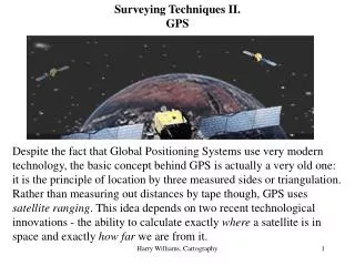
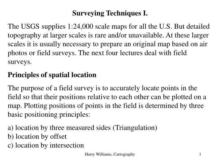
Surveying Techniques I. The USGS supplies 1:24,000 scale maps for all the U.S. But detailed topography at larger scales is rare and/or unavailable. At these larger scales it is usually necessary to prepare an original map based on air photos or field surveys. The next four lectures deal with field surveys. Principles of spatial location The purpose of a field survey is to accurately locate points in the field so that their positions relative to each other can be plotted on a map. Plotting positions of points in the field is determined by three basic positioning principles: a) location by three measured sides (Triangulation)b) location by offsetc) location by intersection Harry Williams, Cartography
In each case, the baseline A-B is in a known location (can be mapped); X is the additional point you are trying to map. Harry Williams, Cartography
Triangulation is based on having three measured distances (AB the base line), AX and BX. Once the location of X is fixed it can be used to build additional triangles. Points A and B are “known” points (can be plotted on a map). Location by offset is based on having a bearing (angle) and distance from a known point to an unknown point (the known point could be a measured distance along a known base line AB or it could be a bench mark, for example). Intersection is based on having two bearings from two known points to an unknown point (the two known points are usually at each end of a base line AB). Because distances are not required, this methods works wherever there is a line of sight (e.g. across lakes, rivers, canyons etc.). X A B Harry Williams, Cartography
Planimetric Position. All of these survey techniques are designed to locate objects in their correct planimetric position (horizontal distances between all objects on map are correct). This is not the same as ground distance, which is affected by slope. Maps are planimetric. A B Map distance A Ground distance B Harry Williams, Cartography
Adding The Third Dimension. The abney level is a small hand-held level designed to measure angles in the vertical plane. It can be used to measure the heights of features such as cliffs, trees or buildings, or the slope of the ground. Once the angle between the object and the observer is obtained, vertical heights can be determined by using simple trig functions. Height of building = Tan 20o x 200 m = 0.346 x 200 m = 72.8 m 20o 200 m Harry Williams, Cartography
The Surveyor’s Level (or Transit). This is basically a telescope mounted on a tripod. The telescope can be leveled, so that the central cross hair is aligned to a level plane and can be used to calculate height. Additional upper and lower cross hairs are used to calculate distance. The telescope is mounted on a swivel allowing rotation in a horizontal plane. View level upper crosshaircentral crosshair lower crosshair Horizontal plane Harry Williams, Cartography
View through the level: Graduated staff 8 7.8 feet – used for distance calculation 7 6.8 feet – used for height calculation 6 5.8 feet – used for distance calculation 5 Distance = upper crosshair – lower crosshair x 100 = 7.8 – 5.8 feet = 2 feet x 100 = 200 feet. (Note: distance calculation varies from level to level). Harry Williams, Cartography
Calculating height:The level gives relative heights – these can be tied to a nearby bench mark or spot height to give absolute heights. For example, if point C was a bench mark at 200 m, then point B would be at 202.74 m. Harry Williams, Cartography
Total Station Surveying: A total station is a survey instrument that can measure horizontal and vertical angles, slope, and horizontal and vertical distances. Measurements recorded by the total station will produce an x, y, and z value. The x-value represents the easting ing, the y-value represents the northing, and the z-value represents the elevation. Harry Williams, Cartography
NORTH Y Z X EAST Harry Williams, Cartography
reflector The total station works by firing an infrared laser beam at a reflector mounted on a stadia rod. The distance between the total station and the reflector is calculated based on the time taken for the beam to reflect back to the total station. Total stations were originally developed for the construction industry – e.g. surveying new roads, laying out building foundations, utility lines etc.. Harry Williams, Cartography
The total station calculates change in height using trigonometry: Harry Williams, Cartography
Horizontal position is based on location by offset: the total station calculates the angle and distance from its location to an unknown point. Harry Williams, Cartography
Example based on UTM: NORTH ANGLE TOTAL STATION:UTM = 3676595m N 672156m E Y=150m; X=70m UNKNOWN POINT UTM=3676595-150 3676445m N 672156+70 672226m E Y DISTANCE X Harry Williams, Cartography
Most total stations have the ability to record survey data as a digital file, which can be imported to a PC-based CAD or GIS program. MAP Harry Williams, Cartography
Why use a total station? Accuracy: total stations are very accurate (can be around 1 cm horizontal and vertical accuracy over distances of around 2 miles. GPS can be fairly accurate for horizontal positioning (e.g. around 1 m), but are less accurate for vertical position (e.g. 5x less accurate than for horizontal position) (Note: very expensive GPS systems can obtain 1 cm horizontal accuracy and, presumably, 5 cm vertical accuracy). Harry Williams, Cartography
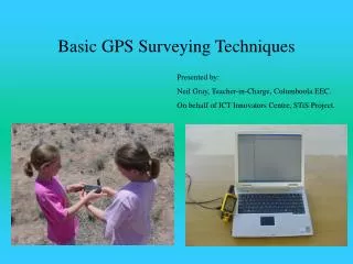
When do you use a total station? For mapping small areas (the range of a total station is around 2 miles or so – assuming you have good lines of sight). A good example would be mapping an archaeological dig site. There are many other applications in earth science that require great accuracy e.g. monitoring cliff erosion, glacier movement, coastal marsh sedimentation, changes in beach profiles, sand dune movement.. And so on. Harry Williams, Cartography