Download
1 / 11
110 likes | 210 Vues
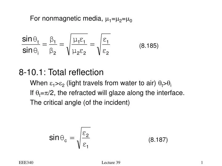
For nonmagnetic media, m 1 = m 2 = m 0 8-10.1: Total reflection When e 1 > e 2 (light travels from water to air) q t > q i If q t = p /2, the refracted will glaze along the interface. The critical angle (of the incident). (8.185). (8.187). What happens when q i > q c ?

E N D
For nonmagnetic media, m1=m2=m0 • 8-10.1: Total reflection • When e1>e2 (light travels from water to air) qt>qi • If qt=p/2, the refracted will glaze along the interface. • The critical angle (of the incident) (8.185) (8.187) Lecture 39
What happens when qi>qc? • qt must be a complex! • Note: sinqt is still real and the phase matching condition is • still held, i.e. • The propagation interface is different for qi<qc and qi>qc. (8.189) Lecture 39
The propagation factor • Where • Note this attenuation is not from lossy material! Even in • lossless case, this alpha exists. Lecture 39
Example 8.14: A dielectric slab is used to guide light or EM waves. Determine the minimum er so that the light cannot escape once it is trapped. • Solution: • And • Since (8.193) Lecture 39
From Snell’s law (8.186) • From (8.193) and (8.194), • Ie: • Make (8.194) Lecture 39
8-10.3: Parallel polarization • The incident fields • Reflected fields • The transmitted fields (8.213) (8.214) (8.215) (8.216) (8.217) (8.218) Lecture 39
Boundary conditions at z=0 lead to (8.221) (8.222) (8.223) Lecture 39
Chapter 9: Transmission Lines • 9-1: Introduction • Power lines at 60 Hz • Two-wire (twin-wire) • Parallel plate • Coaxial • Strip and/or microstrip lines • Transmission line study was originated in power lines • Transmission line equations were derived from distributed circuit concepts. • These equation can be derived from uniform plane wave of Chapter 8. • Transmission line theory is the foundation of packaging and interconnect for high-speed digital circuits and systems Lecture 39
9-3: General Transmission Line Equations • Telegraphers equations • They are derived from circuits, and are easy to remember, since they are generalized Faraday equations. (9.31) (9.33) Lecture 39
In the frequency domain • Note that • For parallel-plate transmission lines (9.35) (9.23) (9.13) (9.15) (9.29) Lecture 39
9-3.1: Wave characteristics on infinite transmission lines. • From the two telegrapher’s equations of (9.35), we have • Where • The impedance (9.36) (9.37) (9.41) Lecture 39