Download
1 / 26
260 likes | 455 Vues
Input and Output. CS 215 Lecture #20. Motivation. I/O devices make computers useful to humans. Input devices may be arbitrarily slow and must have a way to tell the computer that they are ready to supply data.

E N D
Input and Output CS 215 Lecture #20
Motivation • I/O devices make computers useful to humans. • Input devices may be arbitrarily slow and must have a way to tell the computer that they are ready to supply data. • Output devices must have a way of refusing more data until they are ready to receive more.
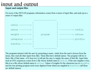
General Categories of I/O • User interface devices. Input devices detect changes and output devices changes the physical world. • Input devices: mouse, keyboard • Output devices: terminal display, printer • Mass storage devices. These devices hold large quantities of data. For example, disks and tape drives. • Gateways and networks. Computers communicate with each other and these communication exhibit delays relative to computer speed. Networks can be treated as if they were conventional I/O devices.
The Keyboard • The keyboard detects when keys are pressed and sends a designated sequence of characters to the computer. A table is used to map the keys to characters. • Some keys like SHIFT, CTRL, ALT, and META either change the mapping of the keyboard or modify the effect of other keys. • The bits are usually sent serially at a rate given in bits per second (bit rate).
The keyboard must have a way of indicating to the computer that it has a character to send. • This is done using extra bits called start bit and stop bit. The start bit signals the beginning of a transmission and the stop bit signals its end. • The computer then knows that data is going to follow after receiving the start bit. The following sequence of bits are saved to an input register. Both start and stop bits are stripped off at the receiving end. • In MAL, we can access the input via $v0 or $2.
The Video Display • Each time a printable character is sent to the display it reacts by displaying the character in the position where the cursor was, and moving the cursor one position to the right. • A terminal consists of a display unit and a keyboard. Thus it is both an input and an output device. • When cr is received, the cursor moves to beginning of the current line and does not scroll. • When nl is received, scrolling is initiated but the cursor does not move. Combining both moves the cursor to the beginning of the next line.
Hard Disk • The disk must first be informed where the data is to be read or written. The disk’s read/write arm seeks to the proper cylinder and rotates to the correct sector. • When the read/write arm is in proper position it then informs the computer that it is ready to receive or transmit. • At this point it can either transmit data or write data.
Hardware: I/O instructions • The hardware implements special instructions to read from/write to I/O devices. • Perhaps lwio (load word I/O) and swio • The devices have a separate address space from memory • lwio $s0, 16 and lw $s0, 16 access different data • lwio $s0, 16 reads the next word from device 16 • lw $s0, 16 reads the word stored in memory location 16. • MIPS does NOT use special I/O instructions
Memory-Mapped I/O • The hardware can be designed in such a way that some memory addresses are not really memory at all but a collection of communication channels to I/O devices. • In memory-mapped I/O, load and store from/to the communication channels provide a means of performing I/O, i.e., load and store instructions with an I/O address are treated as I/O operations. lw $2, KeyboardData sw $5, DisplayData communication channels
MIPS RISC architecture uses memory-mapped I/O. Note that the hardware must support this. • Memory-mapped I/O is one method by which the processor and I/O devices communicate via a common bus. In this case, one common bus for memory and I/O are used with common control lines. • The I/O devices unlike memory may unavailable. If a device is not ready to accept or transmit data then it is said to be not ready or busy. • The processor communicates with I/O using two addresses: one for data exchange and the other to obtain status of the I/O device.
Memory mapped addresses in SPIM keyboard_control = 0xffff0000 display_control = 0xffff0008 keyboard_data = 0xffff0004 display_data = 0xffff000c Data 7 6 5 4 3 2 1 0 Control 1 0 Interrupt enable (1 = enabled) Device busy/ready (1 = ready)
Memory mapped addresses in SPIM • Define the memory mapped constants like this: .data 0xffff0000 keyboard_control: .space 4 keyboard_data: .space 4 display_control: .space 4 display_data: .space 4
wait: lw $14,keyboardstatus beqz $14,wait lw $2,keyboardData wait: lw $14,displaystatus beqz $14,wait sw $2,displayData 1 = ready 0 = busy most significant bit Programmed I/O In programmed I/O, the CPU stays in a loop until the I/O unit indicates that is ready for data transfer or if the CPU has issued a command to the I/O module it must wait until the operation is complete.
Direct Memory Access (DMA) • A controller is a device that has registers and can execute routines on its own given necessary parameters. • A DMA controller is given by the CPU the starting address into which a block of data will be transferred and the amount of data to be transferred. It also has a control register and a status register. • The DMA controller requests memory cycle from the memory controller. During a DMA transfer the CPU executes from cache while control of the memory bus is given to the DMA controller
A code a DMA controller might execute .data count: .word 1024 begin_file: .space 1024 .text initialize: lw $15,count #number of characters la $16,begin_file #address where to store waitloop: lw $14,diskstatus beqz $14, waitloop lb $2,diskdata #read a character sb $2,($16) #store into the array sub $15,1 #decrement counter add $16,1 #adjust array pointer bgtz $15,waitloop
Exception Mechanism • Instead of spin-waiting or doing a regular check whether an I/O device is ready, the I/O device can just inform the CPU that it is ready to receive or transmit data. The I/O device sends an interrupt signal to the system. • In this mechanism, control is transferred to a different program which saves the current state of the interrupted program. The requests are then serviced and control is given back to the interrupted program. This mechanism is called an exception.
An interrupt is one class of exception. • An interrupt can occur at any time. • Hardware and software are needed to support interrupt handling. The hardware must choose the appropriate time in which to interrupt the executing program and transfers control to an exception handler. • The exception handler must save the current state of the interrupted program. • The exception handler also determines which event has caused the exception and decides what should be done based on it.
Since an exception handler can be invoked anytime, an exception handler can not have parameters nor it can return values. • It must also save register values being used by the interrupted program and restore them before returning control to the interrupted program.
Software: Interrupt Driven I/O • Exceptions come in two varieties • Interrupts are generated by hardware • I/O device • Clock • Power down • Traps are generated by code execution • Division by zero • Illegal memory address • System call
How interrupt driven I/O works User code/data Kernel data Display .text . la $a0, A li $v0, 4 syscall . . .data A: .asciiz “cat” Output buffer
How interrupt driven I/O works User code/data Kernel data Display .text . la $a0, A li $v0, 4 syscall . . .data A: .asciiz “cat” Output buffer c a t
How interrupt driven I/O works User code/data Kernel data Display .text . la $a0, A li $v0, 4 syscall . . .data A: .asciiz “cat” Output buffer c c a t
How interrupt driven I/O works User code/data Kernel data Display .text . la $a0, A li $v0, 4 syscall . . .data A: .asciiz “cat” Output buffer ca c a t
How interrupt driven I/O works User code/data Kernel data Display .text . la $a0, A li $v0, 4 syscall . . .data A: .asciiz “cat” Output buffer cat c a t
Role of the Operating System • The operating system is a program that allocates and controls the use of all system resources: the processor, memory, and I/O devices. • Since there are many processes that can run concurrently, the operating system uses interrupt to allocate the processor to different processes periodically -- allowing processes to share processing time with each other. • The exception handler plus other codes used to decide what process should be executed next is called the kernel.
In saving the current values of registers in MIPS RISC architecture, addresses needed to be formed to store them into memory. • The formation of addresses requires the use of registers -- thus $26 and $27 are reserved for the operating system so that when an interrupt is to be serviced there is no need to save the contents of these two registers. • The other type of exception is a trap. A trap occurs when an event happens as a direct result of executing a program, e.g. caused by an overflow or an attempt to access a memory outside of the legal range.