Download
1 / 56
600 likes | 840 Vues
Injection Molding. MFG 355. 15 Ton Injection Molding Machine. Click on frame to start video. 77 Ton Injection Molding Machine. Click on frame to start video. 150 Ton Injection Molding Machine. Click on frame to start video. Feed hopper. Barrel heaters. Nozzle. Screw drive

E N D
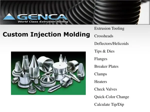
Injection Molding MFG 355
15 Ton Injection Molding Machine Click on frame to start video
77 Ton Injection Molding Machine Click on frame to start video
150 Ton Injection Molding Machine Click on frame to start video
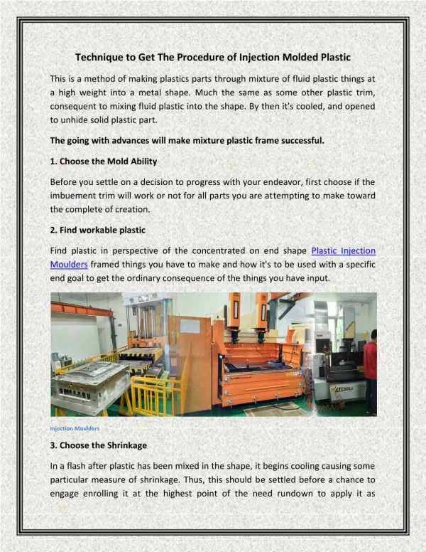
Feed hopper Barrel heaters Nozzle Screw drive arrangement Tool Screw Check valve Screw tip Equipment • Injection Unit
Equipment • Injection Unit
Injection • Parts of the injection screw • Screw • Head and check ring
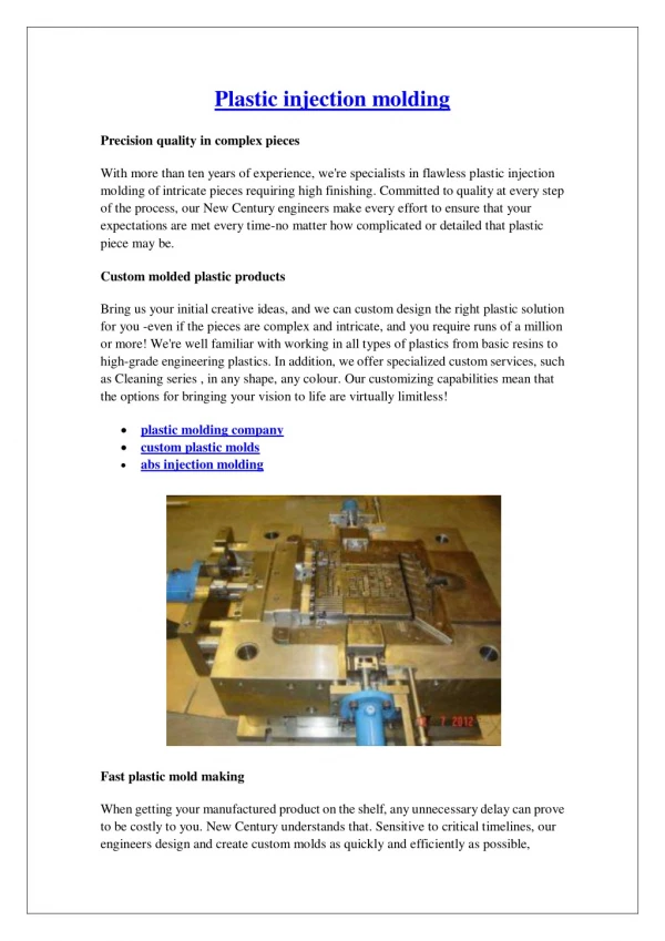
Equipment • Molds
Mold Materials • Aluminum filled epoxy • Aluminum • Tool steel • Stainless steel • Hotwork die steel • Beryllium-copper
Mold Materials • Choice based on critical properties • Machinability • Coefficient of thermal expansion • Specific heat capacity • Thermal conductivity • Density • Hardness (abrasion resistance) • Yield strength • Weldability
Mold Parts • Bases • Standard sizes • Hold mold inserts • Can decrease overall mold costs
Mold Parts • Guide pins • Align mold cavities Guide pins
Mold Parts • Sprue Bushing • Hot sprue • Cold sprue
Mold Parts • Sprue Bushing • Hot sprue
Mold Parts • Sprue Bushing • Cold sprue • Sprue puller
Mold Parts • Sprue Bushing • Cold sprue • Sprue puller
Mold Parts • Runner
Mold Parts • Runner • Layout Improved Balanced “H” Circular Conventional
Mold Parts • Runner • Layout Improved Balanced “H” Circular Conventional
Mold Parts • Runner • Cold well
Mold Parts • Runner
Mold Parts • Gates Submarine Gate Fan or Edge Gate Pinpoint Gate
Mold Parts • Gates Tab Gate Sprue Gate Flash Gate
Mold Parts • Gates Internal Ring Gate External Ring Gate
Mold Parts • Gate
Mold Parts • Gate
Mold Parts • Gate
Mold Parts • Cavity • Where the part is made • Layout is critical to material flow
Mold Parts • Cavity • Knit/weld lines This shows where the weld lines (shown in red) will most likely occur withthe part gated in the center (yellow cone).
Mold Parts • Cooling • Reduce cycle time • Control formation of crystalline areas • Freeze part Mold cavity Cooling lines
Mold Parts • Ejector system Ejector pins Return Springs Ejector Plate
Equipment • Clamping Unit
Equipment • Clamping Unit • Toggle clamping • Hydraulic clamping • Hybrid hydraulic-toggle clamping
Equipment • Clamping Unit
Equipment • Clamping Unit • Toggle system Click on frame to start video
Safety • High clamping forces • High pressure lines • High voltage • High temperatures
Safety • Position switches • Mechanical, hydraulic and electrical • Shields • Lock out/tag out
Material and Product Considerations • Shapes • Possible to do very complex shapes • Structural features • Pins, ribs, bosses, threads, holes • Deep parts are possible • Internal or external threads • Undercuts require sliding mold sections
Material and Product Considerations • Part design • Uniform wall thickness • Helps reduce dimples, shrink marks and distortion • Ribs • Save weight at given strength • No sharp bends • Helps to fill the mold cavity easier • Oversize the mold • Shrinkage amount is dependant on material and additives/fillers
Operations and Control • Temperature of melt • Temperature of mold • Pressure of injection and hold • Injection or fill rate and time • Dwell time • Freeze time • Ejection (dead time)
Special Injection Molding Processes • Coinjection molding • Two separate screws • Two different material selections • Color, strength, flexibility
Special Injection Molding Processes • Coinjection molding 1 2 3
Special Injection Molding Processes • Coinjection molding Part 1 Part 2