Download

1 / 85
870 likes | 911 Vues
WELDED BRIDGE CODE. PB. NAME AND YEAR. CODE OF PRACTICE FOR METAL ARC WELDING IN STRUCTURAL STEEL BRIDGES CARRYING RAIL, RAIL-CUM-ROAD OR PEDESTRIAN TRAFFIC ADOPTED –1972 A & C SLIP NO. 2, YEAR : 1989

E N D
NAME AND YEAR • CODE OF PRACTICE FOR METAL ARC WELDING IN STRUCTURAL STEEL BRIDGES CARRYING RAIL, RAIL-CUM-ROAD OR PEDESTRIAN TRAFFIC • ADOPTED –1972 • A & C SLIP NO. 2, YEAR : 1989 • This code covers design and construction. Some aspects of welded bridge fabrication are also covered under IRS B1
SCOPE • 1.1: Design, construction and inspection of welds made by Manual, automatic or semi automatic metal arc process in new and existing structural steel bridges carrying rail, rail-cum-road or pedestrian traffic • 1.2: Design and construction of welds in mild steel bars used in RCC, and of welds in high tensile steel are not covered by this code. • 1.3: For road bridges, welds shall comply with the standard specifications and code of practice for road bridges issued by the IRC
MATERIAL • 3.1: Fusion welding quality to IS: 2062 • 3.2: Electrodes to IRS: M-28 • Filler wire and flux to IRS M-39 • CO2 welding to RDSO M& C spec. • 3.3: All consummables must be stored with care and as per manufacturer specifications
DRAWINGS • 4.1: Symbols for welding as per IS:813 • 4.2: Drawings and/or welding procedure sheets shall include • Specs of parent metal, and electrodes and/or wire/flux • Locations, sizes, actual lengths and details • Form of joint, angle between fusion faces, gap between parts • Welds – shop or field • Weld procedure – sequence, pre-heating, post heating • Testing and inspection requirements
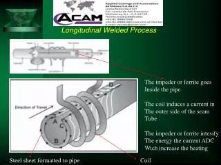
Arc Welding • A pool of molten metal is formed near electrode tip, and as electrode is moved along joint, molten weld pool solidifies in its wake
Flux-Cored Arc Welding Presence or absence of externally supplied shielding gas distinguishes: (1) self‑shielded - core provides ingredients for shielding, (2) gas‑shielded - uses external shielding gases
In submerged arc welding the wire feed and speed of welding head travel are set as per requirement and controlled by motors. In Manual metal arc welding both are controlled by welders. Hence, the weld quality in Submerged Arc Welding will be superior. SAW under process Comparison of depth of penetration
BUTT WELDS • IS:9595, IS:4353 • 5.2 Unsealed butt welds of single V, U, J and bevel types and incomplete penetration butt welds shall not be used • 5.3 Intermittent butt welds shall not be used. • 5.4.1: Sealing or backing: Single V, U, J bevel or square butt welds shall generally be completed by depositing a sealing run of weld metal on the back of the joints
BUTT WELDS • 5.4.2: If weld metal on the back of the joint not possible, then single V, bevel or square butt welds, welded from one side only, may be permitted provided that • Another steel part of the structure or a special steel backing strip is in contact with the back of the joint to ensure complete fusion of the parts to be joined • 5.4.3:In all full penetration butt welds which are to be welded from both sides, the back of the first run shall be gouged out by suitable means to clean sound metal, before welding is started on the gouged out side
BUTT WELDS • Unequal width plates to be welded, or where the difference in thickness of the parts exceeds 25% of the thickness of thinner part or 3 mm (whichever is higher), width/ height to be reduced • slope shall not be steeper than 1 in 5
BUTT WELDS • If Difference in thickness of the parts is less than 25% of the thickness of thinner part or 3 mm (whichever is higher), • sloping weld faces by chamfering the thicker part or by combination of the two methods • 5.5.2 Where the reduction of the dimensions of the thicker part is impracticable, and/or where structures are not designed to withstand dynamic forces, the weld metal shall be built up at the junction with the thicker part to dimension at-least 25% greater than those of the thinner part, or alternatively, to the dimensions of the thicker member
BUTT WELDS • 5.7: Ends of butt joint shall have full throat thickness when parent metal is more than 20 mm thick and preferably in other cases also • Extend ends of the butt welds past the edges of the parts joined by the use of run-on and run-off plates • with similar joint preparation • thickness not less than the thickness of the part joined • length not less than 40 mm • If run on and run off plates removed, ends of the weld shall be finished smooth and flush with the edges of the abutting parts • Cut with abrasive cutter or hacksaw blade
NOT LESS THAN 40 MM RUN-ON AND RUN-OFF PIECES
BUTT WELDS • 5.8: Reinforcement of butt welds – Sufficient convexity not exceeding 3 mm, shall be provided as reinforcement to ensure full cross sectional area at the joint. • Where a flush surface is required, the butt welds shall be first built up as specified above and then dressed flush • 8.1 If butt and fillet welds are combined, the allowable capacity of each shall be separately computed to determine the allowable capacity of the combination. • 8.2 Butt welds in parts or members, subjected to dynamic loading, shall not be supplemented by splice plates attached by fillet welds
FILLET WELD • 6.1.1: Normal Fillet Weld - A normal fillet weld is one in which the depth of penetration beyond the root is less than 2.4 mm • 6.1.2: Deep Penetration Fillet Weld - A deep penetration fillet weld is one in which the depth of penetration beyond the root is 2.4 mm or more • Size - The size of normal fillet weld shall be taken as the minimum leg length • size of a deep penetration fillet weld shall be taken as the minimum nominal leg length plus 2.4 mm
FILLET WELD • 6.2: If the min weld size isgreater than the thickness of the thinner part, the minimum size of the weld shall be equal to the thickness of the thinner part. • The thicker part shall be adequately pre-heated to prevent cracking of the weld • Where the thicker part is more than 50 mm, special precautions like pre-heating as per IS: 9595 shall be taken to ensure weld soundness
FILLET WELD • 6.3: Effective throat thickness - The effective throat thickness of a fillet weld shall be taken as ‘K’ times fillet size where ‘K’ is a constant, given in as per Fig. 13, for different angles between fusion faces. • All fillet welds shall have a flat or convex face • Convexity shall not exceed the value given by the formula 0.1S + 0.76 mm, where S is size of weld in mm • 6.4 Angle between fusion faces - Fillet weld shall not be used for connecting parts, whose fusion faces form an angle of more than 1200 or less than 600 • unless such welds are demonstrated by practical tests to develop the required strength
FILLET WELD • 6.5 Effective length: Length which has the specified size and required throat thickness • actual length of the weld minus twice the weld size • No deduction for end and side fillets, which are returned continuouslyaround the corner for a minimum length of twice the weld size • 6.6 Effective area: The effective area of a fillet weld shall be the effective throat thickness multiplied by the effective length • 6.7 Minimum length: not be less than four times the size of the weld, subject to minimum of 40 mm
INTERMITTENT FILLET WELD • 6.8.1: Intermittent fillet welds may be used in structures not subjected to dynamic loading • 6.8.2: Except for connecting intermediate stiffeners to webs of beams and girders, subject to • 6.8.4 Chain intermittent welding is to be preferred to staggered intermittent welding • 6.8.5: Distance between staggered welds shall not exceed 12 times the thickness of the thinner part and shall in no case exceed 150 mm
LAP JOINTS • 6.14.1: Minimum overlap of parts in stress carrying lap joints shall be four times the thickness of the thinner part. • Unless opening out of the parts is prevented, they shall be connected by at least two transverse or two longitudinal fillet welds
JUNCTION OF WELDS • 9.1: Cope hole is a semi circular notch in between web plate and flange plate to disconnect junction of welds • 9.2: Cope hole not reqd to be provided, if: • Butt welds in flanges and web are made by automatic sub-merged arc welding prior to assembling web and flanges together, • Weld reinforcement is dressed flush both at top and bottom by grinding/machining and • Weld is tested by radiographic/ultrasonic method.
SURFACE PREPARATION • 11.2: For Manual Welding: Tolerances on limits of gap and root face should be ±1 mm on the specified dimensions for material upto and including 12 mm thick and ±2 mm for material over 12 mm thick. • The tolerance on the included angle between the fusion faces of a V preparation is recommended to be ±5 degree and for U and J preparations + 10 degree. • For automatic process, closer limits are necessary and particular requirements depend on the characteristics of the process.
SURFACE PREPARATION • Fusion faces shall be free from • 11.3: cracks, notches or other irregularities • 11.4: heavy scale, moisture, oil, paint or any other substance • 12.1: Parts to be assembled: so that joints are easily accessible and visible to the operator • 12.2: Jigs and manipulators: so that the welding can be carried out in the most suitable position
ASSEMBLY FOR WELDING • 13.1: Fatigue strength of welded structures depends upon the constructional details, this shall be decided before the permissible stresses and consequently the size of members and weld sizes are determined • 13.3: Butt welds - Stresses in butt welds shall not exceed the permissible stresses of the parent metal as specified in IRS Steel Bridge Code
ASSEMBLY FOR WELDING • 13.4.1: The basic permissible stress in fillet welds based on a thickness equal to the throat thickness shall be 100 N/mm2 (10.2 kg/mm2) • when subjected to shear stress in two directions, the actual stress shall be taken as the vector sum of the separate shear stresses • 13.4.2: Above shall not exceed the relevant values specified in Table for Class ‘G’ Constructional details • 14.1 The permissible stresses for field welds shall be reduced to 80%. • Field welds shall not be adopted for bridges carrying road/railway loading without the specific approval of the Board • 14.2 If over-head welds are unavoidable, the stresses permitted shall be 80%
ASSEMBLY FOR WELDING • 14.3 In structures subjected to dynamic loading, tensile or shear stresses in butt welds < 66% of the permissible stresses, unless the welds are examined radiographically, ultrasonically or other NDT methods • 15.4.3 Sizes or lengths of fillet welds shall be sufficient to provide for better distribution of stress. Excessive sizes or lengths shall not be specified • 15.4.2 Accumulation of weld joints in a single location shall be avoided
STRENGTHENING OF EXISTING BRIDGES • 17.2: Where a compression member is strengthened by welding while under load, the work shall be carried out in such a way that – • The r of flange is substantially increased; and • Large compression shrinkage stresses are not induced in the extreme fibers • 17.3: Strengthening of existing bridges by welding shall not be done unless tests prove that the parent metal is suitable for the purpose • 17.4: The details of design for strengthening shall be made taking into consideration the weakening effect of stress raisers on the fatigue strength of the parent metal • 17.5: If material is added to a member carrying dead load stress in excess of 19.6 N/mm2 for strengthening, it is desirable to relieve the member of dead load stress
STRENGTHENING OF EXISTING BRIDGES • 17.6: Where the dead load stress is not relieved, the permissible stress in the new material added for strengthening shall be the allowable unit stress in the original member minus the dead load stress in the original member • 17.7: When welding is used for strengthening an existing riveted or bolted connection, the rivets shall be assumed to carry the dead load and welding is carried out without relieving the dead load stress • In case the rivets or bolts are overstressed even by dead load, or the strengthening is done after relieving the dead load stress, the weld shall be designed to carry all loads including the dead load
APPROVAL AND TESTING OF WELDING PROCEDURES • 19.1 Welding procedure test shall be carried out in accordance with IS:7307(Part-I) to demonstrate, by means of a specimen weld of adequate length on a steel representative of that to be used, so as to confirm that satisfactory weld is achievable with the welding procedure to be used for fabrication • 19.2: Provisions of IS: 9595 and IS: 4353, shall generally be followed, as applicable, for welding procedure, details of workmanship, correction of weld faults, peening, painting, etc • 19.3 In addition to the provisions of IS: 4353 the Inspector may, where deemed necessary, require a sample joint and macro-etch to determine the welding quality: • Welding current ±10% • Arc Voltage ± 7% • Speed of travel ±15% • 20.1 The welders shall be trained in accordance with IS: 817. The welders shall be subjected to appropriate qualifying tests specified in IS: 7310 (Pt-I)