Download
1 / 29
300 likes | 430 Vues
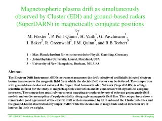
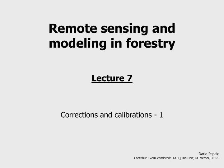
Remote sensing and modeling in forestry Lecture 7 Corrections and calibrations - 1. Dario Papale Contributi: Vern Vanderbilt, TA- Quinn Hart, M. Meroni, CCRS. Images corrections.

E N D
Remote sensing and modeling in forestry Lecture 7 Corrections and calibrations - 1 Dario Papale Contributi: Vern Vanderbilt, TA- Quinn Hart, M. Meroni, CCRS
Images corrections Data collected by remote sensing sensors need, before their use in our applications, a number of corrections in order to remove or reduce disturbances and distortions added during the acquisition and transission to the receiving stations. This pre-processing step can be split in three main corrections classes: Radiometric corrections Atmospheric corrections Geometric corrections
Radiometric corrections To calibrate the sensors and remove the errors due to problems in the data acquisition and transmission. Can be classified in: Radiometric calibration Sensor equalization (de-striping) Problems with single pixels not acquired
Detector DN Filter 16 t0 to t1 25 t1 to t2 t2 to t3 10 EM energy EM energy that reach the detector generate an electric signal. This signal is sampled in a time interval (dt) and recorded as digital number (DN). Only a subset of wavelength pass through the filter and reach the detector. They are out “spectral band” EM signal quantization To define the DN a function like DN = f (L) is used. In the radiometric calibration we want to calculate the energy: L = g (DN)
Lmax Ll [Wm-2sr-1mm-1] Lmin gain offset DN 0 255 Radiometric calibration L = Lmin + (Lmax – Lmin)/255 * DN L = a + b * DN L = offset + gain * DN
Ll [Wm-2sr-1mm-1] gain offset DN 0 255 Radiometric calibration L = offset + gain * DN Each spectral band has own gain and offset that must be used to convert DN in energy at the sensor (W m-2 sr-1µm-1).
Sensor equalization and de-striping This is a problem of all the sensors that have lines of detectors. Each detector can have small differences in the sensitivity to the energy that reach the sensor. This can originate a striping effect in the image that is visible in particular in the homogeneous areas. Could be reduced using onboard calibration data that however are not always available.
Sensor equalization and de-striping In general statistical methods are used DN(c,x-y) = corrected DN of pixel x-y DN(nc,x-y) = original DN of pixel x-y Mi and Si = mean and std of the row of the pixel M and S = mean and std of the row of the image There are also others methods, e.g. based on Fourier Analisys or PCA, implemented in mos of the commercial software
Pixel or line not correctly acquired It can be due to lost of signal or power and this creates errors in the images, generally visible as uniform and dark lines/pixels
Lines and pixels correction • The methods are in general easy and not always needed to be applied: • Single pixel can be substituted with the average of the neighbor • Lines with the average of the one before and after • If needed more sophisticated method based on the relation between different spectral bands. • All these methods create clearly artificial values and this must be always considered.
Atmospheric correction Atmospheric gases, aerosols, vapour contribute to absorb and diffuse the Solar radiation arriving on the Earth surface and reflected Absorption Diffusion
Rayleigh scattering Due to particles much smaller than wavelength, in the visible mainly gases molecules. Function of the wavelength, inverse proportion of λ4, it is more important at shorter wavelengths
Atmospheric absorption Due mainly to some os the atmospheric gases like O2, O3, CO2, H2O
Sun-Target-Sensor system E0 Lt τθ0 τθv atmosphere θ0 θv Li ρλ
Transmission τθ0 a is the estintion coefficient that is function of absorption and diffusion I = I0e-αz I = I0e-τ z is the atmosphere depth τ is the atmosphere optical thickness and it is the attenuation of the radiation after that the whole atmosphere has been pass τ = ∫z α(z)dz τθ0 z atmosphere θ0 In this context it is important to consider that the atmosphere thickness is also function of the Sun angle I = I0e-τ/cosθ
Fluxes and angles I0 Is = I0 * cosθ θ Is1 Is2 Is1 = I0 * cos 0° = I0 Is2 = I0 * cos θ; cos θ < 1; Is2 < I0
Reflectance of a surface If to simplify we consider a Lambertian surface… θ0 θv Li ρλ
Radiation and atmosphere Lt is different from Li because also the reflected radiation has to pass through the atmosphere E0 Lt τθ0 τ atmosphere 1 θ0 Li ρλ
Radiation and atmosphere E0 Lp Lt 2 Ed τ τθ0 1 θ0 L p = Path radiance Li ρλ
5 Radiation and atmosphere E0 Lp Lt 1,3,5 4 2 Ed τθ0 τθv atmosphere 1 θ0 θv 3 Li ρλ ρnλ
Atmospheric correction We are interested to the reflected radiation Li and incoming radiation Ei at surface level. For this reason we need to “model” the radiation-atmosphere interaction to estimate transmittance and path radiance Lp. Lp E0 atmosphere Ei Li
Atmospheric correction There are two groups of methods to take into consideration the effect of the atmosphere function of the availability or not of the atmospheric conditions (optical thickness) when the image has been acquired. What we need is to solve this equation:
Methods to correct the atmosphere effect 1 – Image based Make use of the information in the image only They don’t require info about the atmosphere condition 2 – Radiative transfer models Require information about the atmospheric properties when the image has been acquired They are more accurate If we need to correct for the atmosphere effect and using which method is function of the planned use of the data
Methods image based Histogram method Starting from the general equation: Only the path radiance Lp is considered based on the assumption that there is at least one pixel in the image where the reflectance is zero and for this reason the measured value is only path radiance: To do this the lowest DN of the image is substracted to the whole image: Band X
Dark object Methods Similarly to the Histogram method they are based on the fact that there are areas where the surface don’t reflect in a specifci spectral band. In the dark pixel method these areas are identified in the image and the DN considered path radiance. Dark pixels generally used are clear and deep waters (in the visible) and coniferous forest (red and blue).
Methods image based Multitemporal relative correction Starting from the general equation: Only the atmospheric trasmittance effect is considered at time 0 and time 1, and we have: Using an object in the image where we can assume that the reflectance doesn’t change in time (e.g. street asphalt) it is possible to normalize the image acquired at t=1 with the one at t=0 (same atmospheric condition): (reflectance of the stable object)
We can define the coefficients of the regression between DNs at time1 and time 2: The equation id then applied to the image acquired at time 1. forest rock water Methods image based Scatter plot method Based on surfaces with reflectances that don’t change in time and it is used to normalize images acquired in different times. DNt2 DNt1 This is then repeted for all the bands
Radiative Transfer Models Complex methods E0 Lp atmosphere Ed Er Li L s is calculated starting from DN, offset and gain L p , E i and T are measured directly in the field (the optical tickness) and specific models (MODTRAN, 6S…)