Download
1 / 17
170 likes | 302 Vues
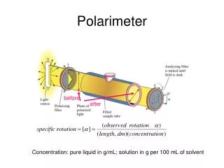
Polarimeter for dEDM experiment. G. Venanzoni Laboratori Nazionali di Frascati for the dEDM collaboration. Workshop on Flavour in the era of LHC – Cern 9-11 Oct 2006. A typical experimental layout contains:. ( φ =0). y. left detector. φ. left and right detectors

E N D
Polarimeter for dEDM experiment G. Venanzoni Laboratori Nazionali di Frascati for the dEDM collaboration Workshop on Flavour in the era of LHC – Cern 9-11 Oct 2006
A typical experimental layout contains: (φ=0) y left detector φ left and right detectors useful for vector polarization x θ z β beam direction target right detector scattering plane A polarization of the beam (p) causes a difference in the rates for scattering to the left compared to the right. For protons (S=1/2): analyzing power (determined by nuclear effects in scattering) governs spin sensitivity vertical component of the polarization unpolarized cross section (determined by nuclear effects in scattering) governs efficiency
A typical experimental layout contains: (φ=0) y left detector φ left and right detectors useful for vector polarization x θ z β beam direction target right detector scattering plane A polarization of the beam (p) causes a difference in the rates for scattering to the left compared to the right. For deuterons (S=1): unpolarized cross section (determined by nuclear effects in scattering) governs efficiency analyzing power (determined by nuclear effects in scattering) governs spin sensitivity
Left-Right and Down-Up Asymmetries • In dEDM experiment we are looking for an increase with time of the vertical polarization(pV,y), over the length of a beam store • By making measurement atf1andf2 = f1+p , we look at the Left-Right (LR) asymmetry, which is sensitive to pV,Y : • In the same way, the Down-Up (DU) asymmetry is sensitive to the component in the plane pV,x • LR Asymmetry due to tensor polarization will have other distinctive signature (phase and oscillation), and is not expected to increase with time eLR will increase with time eDU will oscillate with g-2 frequency
Functional polarimeter elements (must run continuously) Up Iron absorber Left Segmented scintillator Carbon target Right Angle range: 4° - 15° Carbon target is small. Down Left-right asymmetry carries EDM information. • Two possibilities for the polarimeter: • extract using jet in ring onto annular target • tune beam onto annular target • slow extraction into second beam Down-up asymmetry carries information on g-2 precession.
Layout of the Polarimeter (if it were situated on the ring) detector system U “defining aperture” primary target angle L “extraction” target - gas R D R Δ D Target could be Ar gas (higher Z). Detector is far enough away that doughnut illumination is not an acceptance issue: Δ < R. Hole is large compared to beam. Every- thing that goes through hole stays in the ring. (It may take several orbits to stop scattered particle.) Events must imbed far enough from hole to not multiple scatter out of primary target, thus Δ << D. Δ, which is a large fraction of the deuteron range, sets scale for polarimeter. Target “extracts” by Coulomb scattering deuterons onto thick main target. There’s not enough good events here to warrant detectors. Primary target may need to be iris to allow adjustment of position and inner radius. It may also need to be removed during injection.
Polarimeter optimization ingredients • sunp(b)(largest at forward angle) • Vector analyzing power iT11(b) (usually increases at larger angles) • The solution is often a compromise between sunp(b) and iT11(b). It’s common to define a figure of merit (FOM): d= error in the measurement of the pV components
Deuteron data Current design: pd = 1.0 -1.5 GeV/cTd = 250 – 525 MeV • Data: • POMMEat Laboratoire National Saturne (France) (B.Bonin et al. (1990), V.P. Ladygin et al. (1998) ) • Td in (0.175 – 1.8) GeV θ in: [4°, 15°] per Td < 300 MeV • [2°, 20°] per Td > 300 MeV • SMART at RIKEN(Japan) (Y. Satou et al.):Td in (200 – 300)MeV Previous design: pd = 0.7 GeV/c Td = 126 MeV • Data: • S. Kato et al., NIM A 238 (1985) 453-462 • Td in (35 – 70) MeV θ in: [30°, 65°] Data also from Test beam at KVI (Groningen, NL)
wire chambers Iron absorber Carbon target Data from Pomme polarimeter at energies > 200 MeV sunp(b) iT11(b) efficiency (%) average iT11 momentum (GeV/c) Work here. An iron absorber was placed to remove non elastic particles from the scattered flux. At about 700 MeV it loses its effectiveness and iT11 starts to decline.
iT11 s Lab angle (deg) Lab angle (deg) 10o 20o 30o 10o 20o 30o 24o iT11 FOM 14o 18o 5o Data from 270-MeV deuteron elastic scattering – RIKEN Two possibilities: Optimize here: favor larger analyzing power, leverage against systematics 700 MeV Optimize here: favor statistical precision At this energy (p~1 GeV/c) these two choices lead to different angle covarage. But as momentum risesFOM and analyzing power peak together. 700 MeV
Momentum dependence of FOM, iT11 and efficiency The SOLID dots and lines follow the FORWARD peak in the FOM curve. The open/dashed dots and lines follow the analyzing power peak (where there is enough data to use). The AVERAGES shown here integrate over some angle range that covers the relevant feature in FOM or iT11. Satou gets even larger analyzing powers by cutting out more protons and losing “efficiency”. The FOM is down about 30% from the open dots.
Polarimeter statistical error p = 1.5 GeV/c At d=10-29ecm 0.36x0.6 5.7·10-10 rad/s effective beam use fraction 0.5 polarimeter efficiency 2% particles per fill 1012 run time 6·107 s spin coherence time 1000 s 2 years to arrive to sd =10-29ecm
Polarimeter systematic errors (examples of issues) (What other sources arise for a left/right asymmetry?) 1 Displacement / angle errors detectors θ x θ angle shift position shift Remedy: measure on both sides (L/R) flip initial spin opposite sign for EDM accumulation left/right efficiency differences cancel spin detector +/ luminosity differences cancel
Errors that are second-order in θ and u=p++p- A is the analyzing power q is the difference in the mean acceptance angle of the detector btw the + a – polarization states. For LR asymmetry q is the angular shift of the detector/target. Example: With max10-7 and requiring de/e < 10-5 q<0.02o
Polarimeter systematic errors (cont’d) 2 Polarimeter rotation U L R We are helped by the time dependence of εDU and φ-dependence in analysis of segmented detector. target D φ 3 Parity violation Effects start to appear at ε < 10-6 associated with px. We are helped by time dependence.
Polarimeter systematic errors (cont’d) Tensor polarization requires and equal population of m=1 and m=-1 deuterons that is different from m=0. 4 For spin = 1, tensor contributions (t21) detectors The left/right asymmetries oscillate as the spin rotates in the ring plane. They do not grow with time. The effect appears at 10-4 with ~1% tensor contamination of the polarized beam. The left/right asymmetry is maximal along 45° but reverses sign in the perpendicular direction.
Conclusion and outlook • Considerable effort in the past to develop a set of data on which to base the design for the polarimeter (at p=0.7 GeV/c) • At the current design (1.0-1.5 GeV/c) we need to define/study: • “extraction” of the beam • operating momentum of the ring • sensitivity of the polarimeter to different error sources • thickness of the target • segmentation of the detector • Readout and DAQ • Test beam-polarimeter interactions (at COSY), in the case we decide to have the polarimeter in the ring • Prepare (and test) prototype