Download
1 / 4
40 likes | 45 Vues
Pumpbox – 2 blower design. Analyzer flow (30 lpm). Carbon vane pump. Exhaust filter. System vacuum gauge. Spare#1 (30 lpm). Blower#1 Spare lines. Spare#2 (30 lpm). Spare#3 (30 lpm). Spare#4 (30 lpm). rotameters. Blower#2 Stack excess. Stack excess (850 lpm). Pitot tube.

E N D
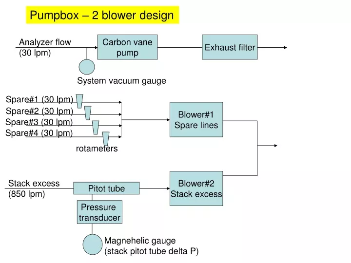
Pumpbox – 2 blower design Analyzer flow (30 lpm) Carbon vane pump Exhaust filter System vacuum gauge Spare#1 (30 lpm) Blower#1 Spare lines Spare#2 (30 lpm) Spare#3 (30 lpm) Spare#4 (30 lpm) rotameters Blower#2 Stack excess Stack excess (850 lpm) Pitot tube Pressure transducer Magnehelic gauge (stack pitot tube delta P)
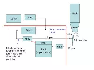
There are 3 pumps in the pump box: • The carbon vane pump pulls the main aerosol system flow (called analyzer flow) through the system (includes nephelometer, psap and CN flow. The carbon vane exhaust is filtered because as the carbon vane pump runs the vanes break down creating small black aerosol. • (2) The spare lines blower pulls 30 lpm through each of the spare lines attached to the splitter. For a basic system there are 4 spare lines although one is used to measure stack T/RH which is used to control the stack heater. • (3) The excess air blower pulls 850 lpm of extra air through the main stack to create isokinetic sampling conditions. • For a basic system a single blower could be used, but having two allows for spare parts and/or system expansion. • There is a time delay relay box in the pumpbox to ensure that all three pumps don’t start at the same time. If they did, the surge could exceed 15A and blow the pumpbox circuit breaker.
Pumpbox – 1 blower design Analyzer flow (30 lpm) Carbon vane pump Exhaust filter System vacuum gauge Spare#1 (30 lpm) Blower#1 Spare lines Spare#2 (30 lpm) Spare#3 (30 lpm) Spare#4 (30 lpm) rotameters Manual valve, restricts past pitot tube so can get flow past rotameters which have higher dP Stack excess (850 lpm) Pitot tube Pressure transducer Magnehelic gauge (stack pitot tube delta P)
There are 2 pumps in the pump box: • The carbon vane pump pulls the main aerosol system flow (called analyzer flow) through the system (includes nephelometer, psap and CN flow. The carbon vane exhaust is filtered because as the carbon vane pump runs the vanes break down creating small black aerosol. • (2) The single blower pulls 30 lpm through each of the spare lines attached to the splitter and 850 lpm of stack excess air. Total flow=970 lpm. A manual valve is used to restrict the flow past the pitot tube so that the blower is able to pull air through the rotameters despite their higher pressure drop. Comments about flows: (a) For a basic system there are 4 spare lines although one is used to measure stack T/RH which is used to control the stack heater. (b) the 850 lpm through the stack creates isokinetic sampling conditions. • There are one or more time delay relay boxes in the pumpbox to ensure that all pumps don’t start at the same time. If they did they could blow the pumpbox circuit breaker.