Download
1 / 78
790 likes | 1.04k Vues
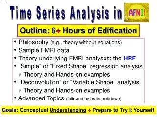
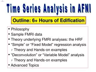
Time Series Analysis in AFNI. Outline: 6+ Hours of Edification. Philosophy Sample FMRI data Theory underlying FMRI analyses: the HRF “Simple†or “Fixed Model†regression analysis Theory and Hands-on examples “Deconvolution†or “Variable Model†analysis Theory and Hands-on examples

E N D
Time Series Analysis in AFNI Outline: 6+ Hours of Edification • Philosophy • Sample FMRI data • Theory underlying FMRI analyses: the HRF • “Simple” or “Fixed Model” regression analysis • Theory and Hands-on examples • “Deconvolution” or “Variable Model” analysis • Theory and Hands-on examples • Advanced Topics
Data Analysis Philosophy • Signal = Measurable response to stimulus • Noise = Components of measurement that interfere with detection of signal • Statistical detection theory: • Understand relationship between stimulus & signal • Characterize noise statistically • Can then devise methods to distinguish noise-only measurements from signal+noise measurements, and assess their reliability • Methods and usefulness depend strongly on the assumptions • Some methods are “robust” against erroneous assumptions, and some are not
FMRI Philosopy: Signals and Noise • FMRI StimulusSignal connection and noise statistics are both poorly characterized • Result: there is no “best” way to analyze FMRI time series data: there are only “reasonable” analysis methods • To deal with data, must make some assumptions about the signal and noise • Assumptions will be wrong, but must do something • Different kinds of experiments require different kinds of analyses • Since signal models and questions you ask about the signal will vary • It is important to understand what is going on, so you can select and evaluate “reasonable” analyses
Meta-method for creating analysis methods • Write down a mathematical model connecting stimulus (or “activation”) to signal • Write down a statistical model for the noise • Combine them to produce an equation for measurements given signal+noise • Equation will have unknown parameters, which are to be estimated from the data • N.B.: signal may have zero strength • Use statistical detection theory to produce an algorithm for processing the measurements to assess signal presence and characteristics • e.g., least squares fit of model parameters to data
Time Series Analysis on Voxel Data • Most common forms of FMRI analysis involve fitting an activation+BOLD model to each voxel’s time series separately (AKA “univariate” analysis) • Some pre-processing steps may do inter-voxel computations • e.g., spatial smoothing to reduce noise • Result of model fits is a set of parameters at each voxel, estimated from that voxel’s data • e.g., activation amplitude, delay, shape • “SPM” = statistical parametric map • Further analysis steps operate on individual SPMs • e.g., combining/contrasting data among subjects
Some Sample FMRI Data Time Series • First: Block-trial FMRI data • “Activation” occurs over a sustained period of time (say, 10 s or longer), usually from more than one stimulation event, in rapid succession • BOLD (hemodynamic) response accumulates from multiple close activations and is large • BOLD response is often visible in time series • Next 4 slides: same brain voxel in 9 imaging runs • black curve (noisy) = data • red curve (above data) = ideal model response • blue curve (within data) = model fitted to data • somatosensory task (finger being rubbed)
model Same Voxel: Runs 1 and 2 (of 9) model fitted to data data Block-trials: 27 s “on” / 27 s “off”; TR=2.5 s; 130 time points/run
Same Voxel: Runs 3 and 4 Block-trials: 27 s “on” / 27 s “off”; TR=2.5 s; 130 time points/run
Same Voxel: Runs 5 and 6 Block-trials: 27 s “on” / 27 s “off”; TR=2.5 s; 130 time points/run
Same Voxel: Runs 7 and 8 Block-trials: 27 s “on” / 27 s “off”; TR=2.5 s; 130 time points/run
Same Voxel: Run 9 and Average of all 9 Activation amplitude and shape are variable! Why???
More Sample FMRI Data Time Series • Second: Event-related FMRI • “Activation” occurs in single relatively brief intervals • “Events” can be randomly or regularly spaced in time • If events are randomly spaced in time, signal model itself looks noise-like • BOLD response to stimulus tends to be weaker since fewer nearby-in-time “activations” have overlapping hemodynamic responses • Next slide: Visual stimulation experiment “Active” voxel shown in next slide
Two Voxel Time Series from Same Run correlation with ideal = 0.56 correlation with ideal = –0.01 Lesson: ER-FMRI activation is not obvious via casual inspection
Hemodynamic Response Function (HRF) • HRF is the idealization of measurable FMRI signal change responding to a single activation cycle (up and down) from a stimulus in a voxel • Response to brief activation (< 1 s): • delay of 1-2 s • rise time of 4-5 s • fall time of 4-6 s • model equation: • h(t) is signal change tseconds after activation 1 Brief Activation
Linearity of HRF • Multiple activation cycles in a voxel, closer in time than duration of HRF: • Assume that overlapping responses add • Linearity is a pretty good assumption • But not apparently perfect — about 90% correct • Nevertheless, is widely taken to be true and is the basis for the “general linear model” (GLM) in FMRI 3 Brief Activations
Linearity and Extended Activation • Extended activation, as in a block-trial experiment: • HRF accumulates over its duration ( 10 s) • Black curve = response to a single brief stimulus • Red curve = activation intervals • Green curve = summed up HRFs from activations • Block-trials have larger BOLD signal changes than event-related experiments 2 Extended Activations
Convolution Signal Model • FMRI signal we look for in each voxel is taken to be sum of the individual trial HRFs • Stimulus timing is assumed known (or measured) • Resulting time series (blue curves) are called the convolution of the HRF with the stimulus timing • Must also allow for baseline and baseline drifting • Convolution models only the FMRI signal changes 22 s 120 s • Real data starts at and • returns to a nonzero, • slowly drifting baseline
Simple Regression Models • Assume a fixed shape h(t) for the HRF • e.g., h(t) = t8.6 exp(-t/0.547) [MS Cohen, 1997] • Convolved with stimulus timing (e.g., AFNI program waver), get ideal response function r(t) • Assume a form for the baseline • e.g., a + bt for a constant plus a linear trend • In each voxel, fit data Z(t) to a curve of the form Z(t) a + bt + r(t) • a, b, are unknown parameters to be calculated in each voxel • a,b are “nuisance” parameters • is amplitude of r(t) in data = “how much” BOLD
Simple Regression: Example Constant baseline: a Quadratic baseline: a+bt+ct2 • Necessary baseline model complexity depends on duration of continuous imaging — e.g., 1 parameter per 100 seconds
Multiple Stimuli = Multiple Regressors • Usually have more than one class of stimulus or activation in an experiment • e.g., want to see size of “face activation” vis-à-vis “house activation”; or, “what” vs. “where” activity • Need to model each separate class of stimulus with a separate response function r1(t),r2(t), r3(t), …. • Each rj(t) is based on the stimulus timing for activity in class number j • Calculate a jamplitude = amount of rj(t) in voxel data time seriesZ(t) • Contrast s to see which voxels have differential activation levels under different stimulus conditions • e.g., statistical test on the question 1–2 = 0 ?
Multiple Regressors: Cartoon • Red curve = signal model for class #1 • Green curve = signal model for #2 • Blue curve = 1#1+2#2 where 1 and 2 vary from 0.1 to 1.7 in the animation • Goal of regression is to find 1 and 2 that make the blue curve best fit the data time series • Gray curve = 1.5#1+0.6#2+noise = simulated data
Multiple Regressors: Collinearity!! • Green curve = signal model for #1 • Red curve = signal model for class #2 • Blue curve = signal model for #3 • Purple curve = #1+#2+#3 which is exactly = 1 • We cannot — in principle or in practice— distinguish sum of 3 signal models from constant baseline!! No analysis can distinguish the cases Z(t)=10+ 5#1 and Z(t)= 0+15#1+10#2+10#3 and an infinity of other possibilities Collinear designs are bad bad bad!
Multiple Regressors: Near Collinearity • Red curve = signal model for class #1 • Green curve = signal model for #2 • Blue curve = 1#1+(1–1)#2 where 1varies randomly from 0.0 to 1.0 in animation • Gray curve = 0.66#1+0.33#2 = simulated data with no noise • Lots of different combinations of #1 and #2 are decent fits to gray curve Red & Green stimuli average 2 s apart Stimuli are too close in time to distinguish response #1 from #2, considering noise
Equations: Notation • Will generally follow notation of Doug Ward’s manual for the AFNI program 3dDeconvolve • Time: continuous in reality, but in steps in the data • Functions of continuous time are written like f(t) • Functions of discrete time expressed like where n=0,1,2,… and TR=time step • Usually use subscript notion fn as shorthand • Collection of numbers assembled in a column is a vector and is printed in boldface:
Equations: Single Response Function • In each voxel, fit data Zn to a curve of the form Zn a + btn + rn for n=0,1,…,N-1 (N=# time pts) • a, b, are unknown parameters to be calculated in each voxel • a,b are “nuisance” baseline parameters • is amplitude of r(t) in data = “how much” BOLD • Baseline model might be more complicated for long (> 200 s) continuous imaging runs: • T < 300 s: a+bt+ct2 • Longer: a+bt+ct2 + T/200 low frequency components • Might also include as extra baseline components the estimated subject head movement time series, in order to remove residual contamination from such artifacts
Equations: Multiple Response Functions • In each voxel, fit data Zn to a curve of the form • j is amplitude in data of rn(j)=rj(tn) ; i.e., “how much” of jth response function in in the data time series • In simple regression, each rj(t) is derived directly from stimulus timing and user-chosen HRF model • In terms of stimulus times: • If stimulus occurs on the imaging TR time-grid, stimulus can be represented as a 0-1 time series: where sk(j)=1 if stimulus #j is on at time t=kTR, and sk(j)=0 if #j is off at that time:
Equations: Matrix-Vector Form • Express known data vector as a sum of known columns with unknown coefficents: ‘’means “least squares” or or the “design” matrix z depends on the voxel; R doesn’t
Visualizing theRMatrix • Can graph columns, as shown below • But might have 20-50 columns • Can plot columns on a grayscale, as shown at right • Easier to show many columns • In this plot, darker bars means larger numbers response to stim B column #4 response to stim A: column #3 linear trend: column #2 constant baseline: column #1
Solving zR for • Number of equations = number of time points • 100s per run, but perhaps 1000s per subject • Number of unknowns usually in range 5–50 • Least squares solution: • denotes an estimate of the true (unknown) • From , calculate as the fitted model • is the residual time series = noise (we hope) • Collinearity: when matrix can’t be inverted • Near collinearity: when inverse exists but is huge
Simple Regression: Recapitulation • Choose HRF model h(t) [AKA fixed-model regression] • Build model responses rn(t)to each stimulus class • Using h(t) and the stimulus timing • Choose baseline model time series • Constant + linear + quadratic + movement? • Assemble model and baseline time series into the columns of the R matrix • For each voxel time series z, solve zRfor • Individual subject maps: Test the coefficients in that you care about for statistical significance • Group maps: Transform the coefficients in that you care about to Talairach space, and perform statistics on these values
Sample Data Analysis: Simple Regression • Enough theory (for now: more to come later!) • To look at the data: typecd AFNI_data1/afni ; then afni • Switch Underlay to dataset epi_r1 • Then Sagittal Image and Graph • FIMPick Ideal ; then click afni/ideal_r1.1D ; then Set • Right-click in image, Jump to (ijk), then 29 11 13, then Set • Data clearly has activity in sync with reference • Data also has a big spike, which is annoying • Subject head movement!
Preparing Data for Analysis • Six preparatory steps are possible • Image registration (realignment): program 3dvolreg • Image smoothing: program 3dmerge • Image masking: program 3dClipLevel or 3dAutomask • Conversion to percentile: programs 3dTstat and 3dcalc • Censoring out time points that are bad: program 3dToutcount or 3dTqual • Catenating multiple imaging runs into 1 big dataset: program 3dTcat • Not all steps are necessary or desirable in any given case • In this first example, will only do registration, since the data obviously needs this correction
Data Analysis Script • waver creates model time series from input stimulus timing in file epi_r1_stim.1D • Plot a 1D file to screen with 1dplot epi_r1_ideal.1D 3dvolreg (3D image registration) will be covered in a later presentation • 3dDeconvolve = regression code • In file epi_r1_decon: waver -GAM \ -input epi_r1_stim.1D \ -TR 2.5 \ > epi_r1_ideal.1D 3dvolreg -base 2 \ -prefix epi_r1_reg \ -1Dfile epi_r1_mot.1D \ -verb \ epi_r1+orig 3dDeconvolve \ -input epi_r1_reg+orig \ -nfirst 2 \ -num_stimts 1 \ -stim_file 1 epi_r1_ideal.1D \ -stim_label 1 AllStim \ -tout \ -bucket epi_r1_func \ -fitts epi_r1_fitts • Name of input dataset • Index of first sub-brick to process • Number of input model time series • Name of first input model time series file • Name for results in AFNI menus • Indicates to output t-statistic for weights • Name of output “bucket” dataset (statistics) • Name of output model fit dataset
Contents of.1D files epi_r1_stim.1D epi_r1_ideal.1D 0 0 0 0 0 0 0 0 0 0 0 0 0 0 0 0 0 0 1 0 1 24.4876 1 122.869 1 156.166 1 160.258 1 160.547 1 160.547 1 160.547 0 160.547 0 136.059 0 37.6781 0 4.38121 0 0.288748 0 0 0 0 … … • 1 line per time point • TR=2.5 s • 0=stim OFF • 1=stim ON • Note that “ideal” is delayed from stimulus • Graphs at right created with 1dplot
To Run Script and View Results • type source epi_r1_decon ; then wait for programs to run • type afni to view what we’ve got • Switch Underlay to epi_r1_reg (output from 3dvolreg) • Switch Overlay to epi_r1_func (output from 3dDeconvolve) • Sagittal Image and Graph viewers • FIMIgnore2 to have graph viewer not plot 1st 2 time pts • FIMPick Ideal ; pick epi_r1_ideal.1D (output from waver) • Define Overlay to set up functional coloring • OlayAllstim[0] Coef (sets coloring to be from model fit ) • ThrAllstim[0] t-s (sets threshold to be model fit t-statistic) • See Overlay (otherwise won’t see the function!) • Play with threshold slider to get a meaningful activation map (e.g., t=4 is a decent threshold)
More Viewing the Results • Graph viewer: OptTran 1DDataset #N to plot the model fit dataset output by 3dDeconvolve • Will open the control panel for the Dataset #N plugin • Click first Input on ; then choose Dataset epi_r1_fitts+orig • Also choose Color dk-blue to get a pleasing plot • Then click on Set+Close (to close the plugin panel) • Should now see fitted time series in the graph viewer instead of data time series • Graph viewer: click OptDouble PlotOverlay on to make the fitted time series appear as an overlay curve • This tool lets you visualize the quality of the data fit • Can also now overlay function on MP-RAGE anatomical by using Switch Underlay to anat+orig dataset • Probably won’t want to graph the anat+orig dataset!
Stimulus Correlated Movement? • Extensive “activation” (i.e., correlation of data time series with model time series) along the top of the brain is an indicator of stimulus correlated motion artifact • Can remain even after registration, due to errors in registration, magnetic field inhomogeneities, etc. • Can be partially removed by using the estimated movement history (from 3dvolreg) as additional baseline model functions • 3dvolreg saved the motion parameters estimates into file epi_r1_mot.1D • For fun: 1dplot epi_r1_mot.1D
Removing Residual Motion Artifacts • Last part of script epi_r1_decon: 3dDeconvolve \ -input epi_r1_reg+orig \ -nfirst 2 \ -num_stimts 7 \ -stim_file 1 epi_r1_ideal.1D \ -stim_label 1 AllStim \ -stim_file 2 epi_r1_mot.1D'[0]' \ -stim_base 2 \ -stim_file 3 epi_r1_mot.1D'[1]' \ -stim_base 3 \ -stim_file 4 epi_r1_mot.1D'[2]' \ -stim_base 4 \ -stim_file 5 epi_r1_mot.1D'[3]' \ -stim_base 5 \ -stim_file 6 epi_r1_mot.1D'[4]' \ -stim_base 6 \ -stim_file 7 epi_r1_mot.1D'[5]' \ -stim_base 7 \ -tout \ -bucket epi_r1_func_mot \ -fitts epi_r1_fitts_mot } These new lines add 6 regressors to the model and assign them to the baseline (-stim_base option) Output files: take a moment to look at results
Some Results: Before and After No: movement parameters are not in baseline model Yes: movement parameters are in baseline model t-statistic threshold set to a p-value of 10-4 in both images
Multiple Stimulus Classes • The experiment analyzed here in fact is more complicated • There are 4 related visual stimulus types • One goal is to find areas that are differentially activated between these different types of stimuli • We have 4 imaging runs, 108 useful time points each (skipping first 2 in each run) that we will analyze together • Already registered and put together into dataset rall_vr+orig • Stimulus timing files are in subdirectory stim_files/ • Script file waver_ht2 will create HRF models for regression: cd stim_files waver -dt 2.5 -GAM -input scan1to4a.1D > scan1to4a_hrf.1D waver -dt 2.5 -GAM -input scan1to4t.1D > scan1to4t_hrf.1D waver -dt 2.5 -GAM -input scan1to4h.1D > scan1to4h_hrf.1D waver -dt 2.5 -GAM -input scan1to4l.1D > scan1to4l_hrf.1D cd .. • type source waver_ht2 to run this script • Might also use 1dplot to check if things are reasonable
Regression with Multiple Model Files • Script file decon_ht2 does the job: 3dDeconvolve -xout -input rall_vr+orig \ -num_stimts 4 \ -stim_file 1 stim_files/scan1to4a_hrf.1D -stim_label 1 Actions \ -stim_file 2 stim_files/scan1to4t_hrf.1D -stim_label 2 Tool \ -stim_file 3 stim_files/scan1to4h_hrf.1D -stim_label 3 HighC \ -stim_file 4 stim_files/scan1to4l_hrf.1D -stim_label 4 LowC \ -concat contrasts/runs.1D \ -glt 1 contrasts/contr_AvsT.txt -glt_label 1 AvsT \ -glt 1 contrasts/contr_HvsL.txt -glt_label 2 HvsL \ -glt 1 contrasts/contr_ATvsHL.txt -glt_label 3 ATvsHL \ -full_first -fout -tout \ -bucket func_ht2 • Run this script by typing source decon_ht2 (takes a few minutes) • Stim #1 = visual presentation of active movements • Stim #2 = visual presentation of simple (tool-like) movements • Stims #3 and #4 = high and low contrast gratings
Regressors for This Script Actions HighC LowC Tools via 1dplot via 1dgrayplot
New Features of 3dDeconvolve - 1 0 108 216 324 -concat contrasts/runs.1D = file that indicates where new imaging runs start -full_first =put full model statistic first in output file, rather than last -fout -tout = output both F- and t-statistics • The full model statistic is an F-statistic that shows how well the sum of all 4 input model time series fits the voxel time series data • The individual models also will get individual F- and t-statistics indicating the significance of their individual contributions to the time series fit
New Features of 3dDeconvolve - 2 -glt 1 contrasts/contr_AvsT.txt -glt_label 1 AvsT -glt 1 contrasts/contr_HvsL.txt -glt_label 2 HvsL -glt 1 contrasts/contr_ATvsHL.txt -glt_label 3 ATvsHL • GLTs are General Linear Tests • 3dDeconvolve provides tests for each regressor separately, but if you want to test combinations or contrasts of the weights in each voxel, you need the -glt option • File contrasts/contr_AvsT.txt = 0 0 0 0 0 0 0 0 1 -1 0 0 (one line with 12 numbers) • Goal is to test a linear combination of the weights • In this data, we have 12 weights: 8 baseline parameters (2 per imaging run), which are first in the vector, and 4 regressor magnitudes, which are from -stim_file options • This particular test contrasts the Actions and Tool s • tests if Actions–Tool 0 } 8 zeros
New Features of 3dDeconvolve - 3 • File contrasts/contr_HvsL.txt = 0 0 0 0 0 0 0 0 0 0 1 -1 • Goal is to test if HighC–LowC 0 • File contrasts/contr_ATvsHL.txt = 0 0 0 0 0 0 0 0 1 1 -1 -1 • Goal is to test if (Actions+ Tool)–(HighC+ LowC) 0 • Regions where this statistic is significant will have had different amounts of BOLD signal change in the activity viewing tasks versus the grating viewing tasks • This is a way to factor out primary visual cortext • -glt_label 3 ATvsHLoption is used to attach a meaningful label to the resulting statistics sub-bricks
Results of decon_ht2 Script • Menu showing labels from 3dDeconvolve run • Images showing results from third contrast: ATvsHL • Play with this yourself to get a feel for it
Statistics from 3dDeconvolve • An F-statistic measures significance of how much a model component reduced the variance of the time series data • Full F measures how much the signal regressors reduced the variance over just the baseline regressors (sub-brick #0 below) • Individual partial-model Fs measures how much each individual signal regressor reduced data variance over the full model with that regressor excluded (sub-bricks #19, #22, #25, and #28 below) • The Coef sub-bricks are the weights (e.g., #17, #20, #23, #26) • A t-statistic sub-brick measure impact of one coefficient
Alternative Way to Run waver • Instead of giving stimulus timing on the TR-grid as a set of 0s and 1s • Can give the actual stimulus times (in seconds) using the -tstim option • waver -dt 1.0 -GAM -tstim 3 12 17 | 1dplot -stdin • If times are in a file, can use -tstim `cat filename` to place them on the command line after -tstim option • This is most useful for event-related experiments Note backward single quotes
Deconvolution Signal Models • Simple or Fixed-shape regression • We fixed the shape of the HRF • Used waver to generate the signal model from the stimulus timing • Found the amplitude of the signal model in each voxel • Deconvolution or Variable-shape regression • We allow the shape of the HRF to vary in each voxel, for each stimulus class • Appropriate when you don’t want to over-constrain the solution by assuming an HRF shape • However, need to have enough time points during the HRF in order to resolve its shape
Deconvolution: Pros and Cons • Letting HRF shape varies allows for subject and regional variability in hemodynamics • Can test HRF estimate for different shapes; e.g., are later time points more “active” than earlier? • Need to estimate more parameters for each stimulus class than a fixed-shape model (e.g., 4-15 vs. 1) • Which means you need more data to get the same statistical power (assuming that the fixed-shape model you would assume was in fact “correct”) • Freedom to get any shape in HRF results can give weird shapes that are difficult to interpret