Download
1 / 25
250 likes | 379 Vues
CMB Polarimetry with BICEP: Probing Inflationary Gravitational Waves. IAS - Polarization 2005 Denis Barkats. Andrew Lange Denis Barkats John Battle James Bock Cynthia Chiang Darren Dowell Greg Griffin Viktor Hristov. Eric Hivon John Kovac Chao-Lin Kuo

E N D
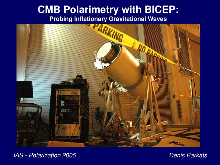
CMB Polarimetry with BICEP: Probing Inflationary Gravitational Waves IAS - Polarization 2005 Denis Barkats
Andrew Lange Denis Barkats John Battle James Bock Cynthia Chiang Darren Dowell Greg Griffin Viktor Hristov Eric Hivon John Kovac Chao-Lin Kuo Pete Mason Hien Nguyen Ian Sullivan Ki Won Yoon Background Imager of Cosmic Extragalactic Polarization Caltech / JPL UC San Diego UC Berkeley Brian Keating Evan Biermann Tom Renbarger Bill Holzapfel Yuki Takahashi CEA Grenoble Cardiff Lionel Duband Peter Ade
What do we need? • Significant advance system sensitivity • Control systematic errors at < 0.1 mK levels • Distinguish CMB from Galactic Foregrounds • Distinguish Gravity-wave Signal from Lensing BICEP State of the CMB polarization field in August 2005 EE and TE polarization WMAP BOOMERANG 03 CBI DASI CAPMAP BB polarization Upper limits ~ 2 mK2 (from DASI, CBI, B03) T/S < 0.36 from CMB+LSS
Overview of the BICEP instrument 10 cm thick Zotefoam window Minimize polarization systematics IR-blocking filters • Simple refractor, no mirrors • Azimuthal symmetry • Alt-az telescope, with continuous boresight rotation • Wide-band polarization modulation with FRMs Cold polyethylene lenses Optimize to 10 < < 400 Feed horn array • Beam sizes ~ 1 deg, 0.6 deg • Field of view ~ 17 deg • Observed sky fraction ~ 5% Faraday rotators PSBs Separate CMB / foregrounds • Two frequency bands at 100 and 150 GHz Helium sorption refrigerator Signal-to-noise considerations • 49 light PSB pairs at 250 mK (98 bolos) • Multiple levels of modulation • South Pole location: long integration over contiguous patch of sky, reduced atmospheric loading Cryostat
Parallel metal lines, Polarization in x-axis Polarization in y-axis New Technology: Polarization Sensitive Bolometers Photon Courtesy of Jamie Bock, NASA JPL
Cryostat and mount Upward-looking cryostat with toroidal LN2 / LHe tanks Long hold time (4-5 days) Helium sorption fridge to cool focal plane to 250 mK Az-El mount + boresite rotation Rotation essential for map cross-linking 4He, 1.5 K 3He, 350 mK 3He, 250 mK Hold time ~ 2 days, cycle ~ 5 hours
25 cm 180 cm Teflon IR-blocking filters Zotefoam window Polyethylene lenses Front-end optics • Telecentric design for flat focal plane • AR-coated filters and lenses • Cross-polarization < 0.01%, instrumental polarization < 1% from physical optics simulations
The BICEP insert Lens tube mounted on top of insert Drop-in focal plane Trussed structure to isolate 250 mK plate from 4 K Cold JFETs for signal buffering, refrigerator, thermal connections to focal plane All RF-sensitive components enclosed in large faraday cage
100 GHz 150 GHz Image: J. Kovac Full focal plane map • 49 spatial pixels = 98 polarization-sensitive bolometers • Divided into 6 similar hextants • Each hextant has 4 pixels at each band • Adjacent hextants measure Q and U.
A closer look at the focal plane Image: K. Yoon Primary beam-defining feed horn (4 K) Faraday rotator module A photon's view of the focal plane Re-expanding horn (4 K) Band-defining metal mesh filters, baffles Polarization- sensitive bolometers Refocusing horn (250 mK)
“150 GHz band” Bandwidth: 41 GHz Optical efficiency:25% “100 GHz band” Bandwidth: 24 GHz Optical efficiency:27.5% Home, sweet (frozen) home: South Pole station, Antarctica
What can BICEP do for you? - Winter 2005 / 2006: deployment to south pole - Return information on polarized foreground emission - Measure EE polarization at intermediate , complementary to current detections BB polarization: if anyone's gonna do it (in the next N years), we will! N ~ number of years before SPIDER, EBEX, CMBpol, Planck etc. 1 year of Planck ~ 6 x sensitivity of 8 years of WMAP BICEP has similar instantaneous sensitivity to polarization as Planck, and is more sensitive to peak BB signal due to concentration on a small patch of sky Detect BB polarization if T/S > 0.05 (assuming “reasonable” integration time), otherwise set a bomber upper limit http://www.astro.caltech.edu/~lgg/bicep_front.htm
Expected BICEP performance System NET ~ 35 uK√s (350 uK√s per PSB, 98 detectors) EE Total integration time: somewhere between 100 days and200 days BB Observed sky fraction ~ 5% Beam width ~ 1 degree T/S = 0.05 and t = 0.17
BICEP ELECTRONICS “DIRTY” DIGITAL COMPARTMENT ELECTRONICS BACKPACK ELECTRONICS BOX RF FILTER “CLEAN” ANALOG COMPARTMENT POWER REGULATORS ROTARY JOINT
TYPICAL BOLOMETER CHARACTERISTICS Upper limit on scanning speed set by the time constant: ~ 0.25 (FWHM) / opt = 10.5 deg/s… is not a limiting factor.
“150 GHz band” Bandwidth: 41 GHz Optical efficiency:25% “100 GHz band” Bandwidth: 24 GHz Optical efficiency:27.5%
QUAD Electronics in Operation VME DAS 128 ch ADC DIO Cards Real time computer Thermometry readout Interface boxes RF-filtering PID Controller Digital B.O.B. Electronics boxes 4 x lockin 1 x bias 1 x F.P. T.C. 1 x GRT amp Power supplies
QUAD Electronics Overview • 96 channels of readout • 62 light bolometers • 4 darks • 3 thermistors • Ample spares • Cold JFET amplifiers • AC biased / lockin demodulation • Focal plane temp. control • Fully computer controlled QUAD Amplifier Box (1 of 4)
QUAD Readout Electronics summary • Bias Generator • AC / DC • Freq: 40 – 200 Hz • Amp: 0.36 mV steps • Fully computer controlled cryostat • Lockin Cards • DC-offset removal • Phase adjustment 45° range at 90 Hz, 7-bit resolution • Fully computer controlled Gain: 100,000 (nominal) 97,000 (at DC) 91,500 (at 90 Hz) • Proven Design • Bolocam • SuZIE • BOOMERANG
BICEP BOLOMETER READOUT ELECTRONICS RF-TIGHT FARADAY CAGE PREAMPS & SIGNAL CONDITIONERS DIGITAL LOCKINS (DLIAS) RL LPF AC / DC BiasGen. COLD JFETS RF FILTER RB RF FILTER ADC MSP RL CPLD RF FILTER SYNCH, HSCK, CMD AC / DC SYNCH, HSCK SPI CONTROLLERS SPI OPTICAL FIBER ETHERNET CARDS DAQ PC ETHERNET HUB
10 cm-thick Zotefoam window OPTICAL CHAIN AND FILTERING 270 K 77 K Teflonblockers 20 K 4 K Polyethylene lenses FRM 250 mK