Download

1 / 46
460 likes | 591 Vues
ΗΜΥ -210: Σχεδιασμός Ψηφιακών Συστημάτων Χειμερινό Εξάμηνο 200 7. VHDL για Σχεδιασμό Συνδυαστικών Κυκλωμάτων. Διδάσκουσα: Μαρία Κ. Μιχαήλ. Πανεπιστήμιο Κύπρου Τμήμα Ηλεκτρολόγων Μηχανικών και Μηχανικών Υπολογιστών. VHDL (revisited).

E N D
ΗΜΥ-210: Σχεδιασμός Ψηφιακών Συστημάτων Χειμερινό Εξάμηνο 2007 VHDL για ΣχεδιασμόΣυνδυαστικών Κυκλωμάτων Διδάσκουσα: Μαρία Κ. Μιχαήλ Πανεπιστήμιο Κύπρου Τμήμα Ηλεκτρολόγων Μηχανικών και Μηχανικών Υπολογιστών
VHDL (revisited) • VHDL is a hardware description language used to specify logic designs. • Sponsored (early 80s) by IEEE and DoD. • Features: • Hierarchical designs • Interface andbehavior specified precisely (and separately) • Algorithmic or hardware-oriented behavior spec • Concurrency, timing, clocking can be modeled; design can be simulated accurately. VHDL για Σχεδιασμό Συνδυαστικών Κυκλωμάτων
VHDL Model Components • A complete VHDL component description requires a VHDL entityand a VHDL architecture: • The entity defines a component’s interface (name, inputs, outputs). • The architecture defines a component’s function. • Several alternative architectures may be developed for use with the same entity. VHDL για Σχεδιασμό Συνδυαστικών Κυκλωμάτων
Simple example: Entity entity My_Component is-- “My_Component”: name of item port(X,Y:inBIT;-- interface specification Z:outBIT); end My_Component; port statement defines inputs and outputs X My_Component Z Comments Y VHDL keywords Identifiers Port Mode Data Type VHDL για Σχεδιασμό Συνδυαστικών Κυκλωμάτων
Simple example: Architecture entity My_Component is-- “My_Component”: name of item Port(X,Y:inBIT;-- interface specification Z:outBIT); end My_Component; Architecture My_Component_Arch of My_Component is begin Z <= ‘1’ when X=‘1’ and Y=‘0’ else ‘0’; end My_Component_Arch; Comments VHDL keywords Corresponding entity Identifiers Z = X•Y’ Port Mode Data Type VHDL για Σχεδιασμό Συνδυαστικών Κυκλωμάτων
VHDL Language elements • Comments: start with --, go to end of line • Keywords (reserved words): entity, port, is, in, out, end, architecture, begin, end, when, else,etc. • Identifiers (user-defined ‘variables’) VHDL για Σχεδιασμό Συνδυαστικών Κυκλωμάτων
Identifiers • May contain A-Z, a-z, 0-9, _ • Must start with letter • May not end with _ • May not include two consecutive _ • VHDL is case insensitive • Sel, sel and SEL refer to same object VHDL για Σχεδιασμό Συνδυαστικών Κυκλωμάτων
Identifier Examples • A2G • valid • 8bit_counter • invalid -- starts with number • _NewValue • invalid -- starts with _ • first# • invalid -- illegal character VHDL για Σχεδιασμό Συνδυαστικών Κυκλωμάτων
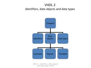
VHDL Data Objects • Constant • Variable • Signal • File* * Not supported by synthesis tools VHDL για Σχεδιασμό Συνδυαστικών Κυκλωμάτων
Characters and Strings • Characters • ‘A’, ‘0’, ‘1’, ‘$’, ’x’, ‘*’ • Strings • “string of characters” • “00101101” • “0X110ZZ1” • Bit Strings • B”011111010110” • O”3726” • X”7D6” VHDL για Σχεδιασμό Συνδυαστικών Κυκλωμάτων
VHDL Data Types • Scalar • Integer • Enumerated • Real (floating point)* • Composite • Array • Record • Access (pointers)* * Not supported by synthesis tools VHDL για Σχεδιασμό Συνδυαστικών Κυκλωμάτων
Scalar Data Types • Integer: • Minimum range for any implementation as defined by standard: - 2,147,483,647 to 2,147,483,647 • Example: assignments to a variable of type integer : ARCHITECTURE test_int OF test IS BEGIN PROCESS (X) VARIABLE a: INTEGER; BEGIN a := 1; -- OK a := -1; -- OK a := 1.0; -- illegal END PROCESS; END test_int; VHDL για Σχεδιασμό Συνδυαστικών Κυκλωμάτων
Scalar Data Type (cont.) • Integer (cont.): • We can also define range of integers. • Examples:type CountValue isrange 0 to 15;type Twenties isrange 20 to 29;type Thirties isrange 39 downto 30; VHDL για Σχεδιασμό Συνδυαστικών Κυκλωμάτων
Scalar Data Types (cont.) • Enumerated: • User specifies list of possible values • Example declaration and usage of enumerated data type : TYPE binary IS ( ON, OFF ); ... some statements ... ARCHITECTURE test_enum OF test IS BEGIN PROCESS (X) VARIABLE a: binary; BEGIN a := ON; -- OK ... more statements ... a := OFF; -- OK ... more statements ... END PROCESS; END test_enum; VHDL για Σχεδιασμό Συνδυαστικών Κυκλωμάτων
Booleans • typebooleanis (false, true); • variable A,B,C: boolean; • C := not A • C := A and B • C := A or B • C := A nand B • C := A nor B • C := A xor B • C := A xnor B VHDL Object Assignment operator for variables VHDL για Σχεδιασμό Συνδυαστικών Κυκλωμάτων
Bits typebitis (‘0’, ‘1’); signal x,y,z: bit; x <= ‘0’; y <= ‘1’; z <= x and y; VHDL Object Assignment operator for variables VHDL για Σχεδιασμό Συνδυαστικών Κυκλωμάτων
Standard Logic type std_logic is ( ‘U’, -- Uninitialized ‘X’ -- Forcing unknown ‘0’ -- Forcing zero ‘1’ ); -- Forcing one • std_logic is part of the ieeepackage • Packages: precompiled VHDL code stored in a directory referred to as library library IEEE; use IEEE.std_logic_1164.all; Must be included in your source code before declaring std_logicdata types VHDL για Σχεδιασμό Συνδυαστικών Κυκλωμάτων
0 31 ... element indices... 0 1 ...array values... Composite Data Types • Array: • Used to group elements of the same type into a single VHDL object • Range may be unconstrained in declaration • Range would then be constrained when array is used • Example declaration for one-dimensional array (vector) : TYPE data_bus IS ARRAY(0 TO 31) OF BIT; VARIABLE X : data_bus; VARIABLE Y : BIT; Y := X(12); -- Y gets value of element at index 12 VHDL για Σχεδιασμό Συνδυαστικών Κυκλωμάτων
VHDL Architecture Structure architecture name_arch of name is begin end name_arch; Signal assignments Processes contain sequential statements, but execute concurrently within the architecture body Concurrent statements Process 1 Concurrent statements Process 2 Concurrent statements VHDL για Σχεδιασμό Συνδυαστικών Κυκλωμάτων
Optional process label VHDL Process P1: process (<sensitivity list) <variable declarations> begin <sequential statements> end process P1; Within a process: Variables are assigned using := and are updated immediately. Signals are assigned using <= and are updated at the end of the process. VHDL για Σχεδιασμό Συνδυαστικών Κυκλωμάτων
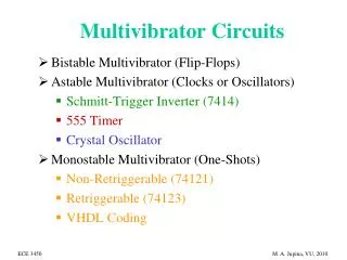
2-to-4 decoder in VHDL: Gate-level diagram VHDL για Σχεδιασμό Συνδυαστικών Κυκλωμάτων
2-to-4 decoder in VHDL: Interface -- 2-to-4 Line Decoder: Structural VHDL Description -- (See Figure 3-13 for logic diagram) library ieee, lcdf_vhdl; use ieee.std_logic_1164.all, lcdf_vhdl.func_prims.all; entity decoder_2_to_4 is port(E_n, A0, A1: in std_logic; D0_n, D1_n, D2_n, D3_n: out std_logic); end decoder_2_to_4; Import library functions Inputs & outputs VHDL για Σχεδιασμό Συνδυαστικών Κυκλωμάτων
2-to-4 decoder in VHDL: Structural Architecture architecture structural_1 of decoder_2_to_4 is component NOT1 port(in1: in std_logic; out1: out std_logic); end component; component NAND3 port(in1, in2, in3: in std_logic; out1: out std_logic); end component; Declare available components VHDL για Σχεδιασμό Συνδυαστικών Κυκλωμάτων
2-to-4 decoder in VHDL: Structural Architecture (cont.) Local signals signal E, A0_n, A1_n: std_logic; begin g0: NOT1 port map (in1 => A0, out1 => A0_n);g1: NOT1 port map (in1 => A1, out1 => A1_n);g2: NOT1 port map (in1 => E_n, out1 => E);g2: NAND3 port map (in1 => A0_n, in2 => A1_n, in3 => E, out1 => D0); g3: NAND3 port map (in1 => A0, in2 => A1_n, in3 => E, out1 => D1); g4: NAND3 port map (in1 => A0_n, in2 => A1, in3 => E, out1 => D2); g5: NAND3 port map (in1 => A0, in2 => A1, in3 => E, out1 => D3); end structural_1; VHDL για Σχεδιασμό Συνδυαστικών Κυκλωμάτων
2-to-4 decoder in VHDL: Dataflow Architecture -- 2-to-4 Line Decoder: Dataflow VHDL Description -- (See Figure 3-14 for logic equations) library ieee, lcdf_vhdl; use ieee.std_logic_1164.all, lcdf_vhdl.func_prims.all; entity decoder_2_to_4 is port(E_n, A0, A1: in std_logic; D0_n, D1_n, D2_n, D3_n: out std_logic); end decoder_2_to_4; VHDL για Σχεδιασμό Συνδυαστικών Κυκλωμάτων
2-to-4 decoder in VHDL: Dataflow Architecture (cont.) architecture dataflow_1 of decoder_2_to_4 is signal A0_n, A1_n: std_logic; begin A0_n <= not A0; A1_n <= not A1; E_n <= not E; D0_n <= not (A0_n and A1_n and E); D1_n <= not (A0 and A1_n and E); D2_n <= not (A0_n and A1 and E); D3_n <= not (A0 and A1 and E); end dataflow_1; VHDL για Σχεδιασμό Συνδυαστικών Κυκλωμάτων
Sel y “00” a “01” b “10” c “11” d Another example:An n-line 4 x 1 multiplexer a(n-1:0) 8-line b(n-1 :0) 4 x 1 y(n-1 :0) c(n-1 :0) MUX d(n-1 :0) sel(1:0) VHDL για Σχεδιασμό Συνδυαστικών Κυκλωμάτων
An n-line 4 x 1 multiplexer:Entity Declaration library IEEE; use IEEE.std_logic_1164.all; entity mux4g is generic(width:positive); port ( a: in STD_LOGIC_VECTOR (width-1 downto 0); b: in STD_LOGIC_VECTOR (width-1 downto 0); c: in STD_LOGIC_VECTOR (width-1 downto 0); d: in STD_LOGIC_VECTOR (width-1 downto 0); sel: in STD_LOGIC_VECTOR (1 downto 0); y: out STD_LOGIC_VECTOR (width-1 downto 0) ); end mux4g; VHDL για Σχεδιασμό Συνδυαστικών Κυκλωμάτων
Sel y “00” a “01” b “10” c “11” d An n-line 4 x 1 multiplexer:Dataflow architecture declaration using a CASE statement architecture mux4g_arch of mux4g is begin process (sel, a, b, c, d) begin case sel is when "00" => y <= a; when "01" => y <= b; when "10" => y <= c; when others => y <= d; end case; end process; end mux4g_arch; Must include ALL posibilities in case statement VHDL για Σχεδιασμό Συνδυαστικών Κυκλωμάτων
Half Adder • Problem: Model a single bit half adder with carry and enable. • Specifications • Inputs and outputs are each one bit • When enable is high, result gets x plus y • When enable is high, carry gets any carry of x plus y • Outputs are zero when enable input is low x carry y Half Adder result enable VHDL για Σχεδιασμό Συνδυαστικών Κυκλωμάτων
Half Adder: Entity Declaration • As a first step, the entity declaration describes the interface of the component • input and output ports are declared ENTITY half_adder IS PORT( x, y, enable: IN bit; carry, result: OUT bit); END half_adder; x carry Half Adder y result enable VHDL για Σχεδιασμό Συνδυαστικών Κυκλωμάτων
Half Adder: Behavioral Architectural Specification • A high level description can be used to describe the function of the adder ARCHITECTURE half_adder_a of half_adder IS BEGIN PROCESS (x, y, enable) BEGIN IF enable = ‘1’ THEN result <= x XOR y; carry <= x AND y; ELSE END IF; END PROCESS; END half_adder_a; • The model can then be simulated to verify correct functionality of the component VHDL για Σχεδιασμό Συνδυαστικών Κυκλωμάτων
x y carry enable result Half Adder: Structural Architectural Specification • As a second method, a structural description can be created from pre-described components • These gates can be pulled from a library of parts, and the functionality, again, can be simulated VHDL για Σχεδιασμό Συνδυαστικών Κυκλωμάτων
Half Adder: Structural Architectural Specification (cont.) ARCHITECTURE half_adder_c of half_adder_Nty IS COMPONENT and2 PORT (in0, in1 : IN BIT; out0 : OUT BIT); END COMPONENT; COMPONENT and3 PORT (in0, in1, in2 : IN BIT; out0 : OUT BIT); END COMPONENT; COMPONENT xor2 PORT (in0, in1 : IN BIT; out0 : OUT BIT); END COMPONENT; FOR ALL : and2 USE ENTITY gate_lib.and2_Nty(and2_a); FOR ALL : and3 USE ENTITY gate_lib.and3_Nty(and3_a); FOR ALL : xor2 USE ENTITY gate_lib.xor2_Nty(xor2_a); -- description is continued on next slide VHDL για Σχεδιασμό Συνδυαστικών Κυκλωμάτων
Half Adder: Structural Architectural Specification (cont.) -- continuing half_adder_c description SIGNAL xor_res : bit; -- internal signal -- Note that other signals are already declared in entity BEGIN A0 : and2 PORT MAP (enable, xor_res, result); A1 : and3 PORT MAP (x, y, enable, carry); X0 : xor2 PORT MAP (x, y, xor_res); END half_adder_c; VHDL για Σχεδιασμό Συνδυαστικών Κυκλωμάτων
Half Adder: Dataflow Architectural Specification • A 3rd method is to use logic equations to develop a data flow description ARCHITECTURE half_adder_b of half_adder_Nty IS BEGIN carry <= enable AND (x AND y); result <= enable AND (x XOR y); END half_adder_b; • Again, the model can be simulated at this level to confirm the logic equations VHDL για Σχεδιασμό Συνδυαστικών Κυκλωμάτων
4-bit adder:Entity declaration -- 4-bit Adder: Behavioral Description library ieee; use ieee.std_logic_1164.all; use ieee.std_logic_unsigned.all; entity adder_4_b is port(B, A : in std_logic_vector(3 downto 0); C0 : in std_logic; S : out std_logic_vector(3 downto 0); C4: out std_logic); end adder_4_b; VHDL για Σχεδιασμό Συνδυαστικών Κυκλωμάτων
4-bit adder:Behavioral Arch. Specification architecture behavioral of adder_4_b is signal sum : std_logic_vector(4 downto 0); begin sum <= ('0' & A) + ('0' & B) + ("0000" & C0); C4 <= sum(4); S <= sum(3 downto 0); end behavioral; 0A3A2A1A0 0B3B2B1B0 0000C0 VHDL για Σχεδιασμό Συνδυαστικών Κυκλωμάτων
Simple combinational function: Dataflow description library ieee; use ieee.std_logic_1164.all; entity func2 is port (x1,x2,x3: in std_logic; f: out std_logic ); end func2 architecture dataflow of func2 is begin f <= (not x1 and not x2 and x3) or (x1 and not x2 and not x3) or (x1 and not x2 and x3) or (x1 and x2 and not x3); end logicfunc; VHDL για Σχεδιασμό Συνδυαστικών Κυκλωμάτων
Dataflow: Full Adder library ieee; use ieee.std_logic_1164.all; entity fulladd is port (Cin, x, y: in std_logic; s, Cout: out std_logic); end fulladd; VHDL για Σχεδιασμό Συνδυαστικών Κυκλωμάτων
Dataflow: Full Adder (cont.) architecture logicfunc of fulladd is begin s <= x xor y xor Cin; Cout <= (x and y) or (Cin and x) or (Cin and y); end logicfunc; VHDL για Σχεδιασμό Συνδυαστικών Κυκλωμάτων
Structural: 4-bit adder library ieee; use ieee.std_logic_1164.all; entity adder4 is -- s = x+y port (Cin: in std_logic; x3,x2,x1,x0: in std_logic; y3,y2,y1,y0: in std_logic; s3,s2,s1,s0: out std_logic; Cout: out std_logic ); end adder4; VHDL για Σχεδιασμό Συνδυαστικών Κυκλωμάτων
Structural: 4-bit adder (cont.) architecture structural of adder4 is signal c1,c2,c3: std_logic; component fulladd port (Cin,x,y: in std_logic; s,Cout: out std_logic); endcomponent; begin stage0: fulladd port map (Cin,x0,y0,s0,c1); stage1: fulladd port map (c1,x1,y1,s1,c2); stage2: fulladd port map (c2,x2,y2,s2,c3); stage3: fulladd port map (Cin=>c3,Cout=cout,x=>x3,y=>y3,s=>s3); end structural; Same order as declaration Custom order VHDL για Σχεδιασμό Συνδυαστικών Κυκλωμάτων
2-to-1 MUX library ieee; use ieee.std_logic_1164.all; entity mux2to1 is port (d0,d1,s: in std_logic; y: out std_logic); end mux2to1; architecture behavioral of mux2to1 is begin with s select y <= d0 when ‘0’, d1 when others; end behavioral; VHDL για Σχεδιασμό Συνδυαστικών Κυκλωμάτων
Decoder library ieee; use ieee.std_logic_1164.all; entity dec2to4 is port (w: in std_logic_vector(1 downto 0); e: in std_logic; y: out std_logic_vector(0 to 3)); end dec2to4; VHDL για Σχεδιασμό Συνδυαστικών Κυκλωμάτων
Decoder (cont.) architecture behavioral of dec2to4 is signal ew: std_logic_vector(2 downto 0); begin ew <= e & w; -- concatenation! with ew select y <= “1000” when “100”, “0100” when “101”, “0010” when “110”, “0001” when “111”, “0000” whenothers; end behavioral; VHDL για Σχεδιασμό Συνδυαστικών Κυκλωμάτων