Download

1 / 61
620 likes | 770 Vues
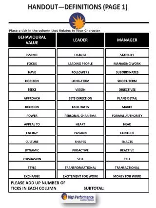
Page 26 of your handout. DITCH TYPES. INTERCEPTOR: Located on a hillsides and at the foot of slopes to intercept runoff to prevent erosion of the cut. ROADSIDE or SIDE DITCH: Located along side a road or airfield, it collects runoff and transports it to a culvert or diversion ditch.

E N D
DITCH TYPES • INTERCEPTOR: Located on a hillsides and at the foot of slopes to intercept runoff to prevent erosion of the cut. • ROADSIDE or SIDE DITCH: Located along side a road or airfield, it collects runoff and transports it to a culvert or diversion ditch. • DIVERSION DITCH: Diverts water away from construction or structures to prevent erosion and flooding.
DITCH SHAPE AND DESIGN CAPACITY Triangular or Vee ditch Installed to handle flows 60 CFS or less. Trapezoidal ditch Installed to handle flows greater than 60 CFS
1.5’ MIN 1 1 Q 60 cfs. or less TRIANGULAR or VEE DITCH ROAD 3 3 SYMMETRICAL “VEE” DITCH Normally a slope of 3:1 ROAD 3 1 NONSYMMETRICAL “VEE” DITCH Normally a slope of 3:1 / 1:1 1.5’ MIN 1 1
Q 60 cfs. TRAPEZOIDALDITCH ROAD 3 3 1.5’ MIN 1 1 Bottom width depends on equipment constructing the ditch: BHL or SEE 2’,HYEX 5’, Dozer / Scraper 10’
Change in elevation high elevation - low elevation Length of ditch Length of ditch = CALCULATING DITCH SLOPE =
T.O. Ditch Characteristics • All ditches will have a minimum depth of 1.5 feet. • Minimum slope to allow ditch to flow properly and be self-cleaning = 0.5 % • Maximum slope ditch will be designed without erosion control = 2% • Standard ditch slope ratios (horz to vert) Roadside 3:1 / 1:1 Airfield 7:1 Diversion 3:1 All others 3:1
INCORRECTLOCATION FILL NATURAL GROUND DITCH LOCATION
CORRECTLOCATION FILL NATURAL GROUND DITCH LOCATION
CONTINUITY EQUATION Q = V x A Q = QUANTITY (cfs. Cubic Feet per Second) V = VELOCITY(fps. Feet Per Second) A = CROSS-SECTIONAL AREA (SQ. FT.)
VELOCITY RELATIONSHIPS • As slope increases, the velocity (V) will increase. • As quantity of runoff (Q) increases while area (A)remains the same, Velocity (V) will increase. • If Manning's n increases (roughness coefficient),velocity (V) will decrease. • If velocity (V) increases then erosion will naturallyincrease.
DITCH DESIGN P.E. 4 Starts on Page 34 of Student Handout, using the procedures from page 27-33 of the Student Handout.
REQUIREMENT: Design a roadside ditch that will handle a flow of 9.2 cfs. Ditch must be 1080 feet long, have a beginning elevation of 82 feet and an ending elevation of 62.6 feet. Soil GMd soil. 1. Q design range: (+/- 5 % of “Q” ) 2. Type of ditch based on Q:_______Bottom Width:_____ft 3. Side slope ratios:_____________________________ 4. Slope:_____________________________
Step 1 Design Range 1. Determine flow requirement. (9.2 cfs) 2. Multiply flow requirement by .05 9.2 x .05 = 0.46 3. Add and subtract this number (0.46) from flow requirement to establish range. 9.2 + 0.46 = 9.66 9.2 - 0.46 = 8.74
REQUIREMENT: Design a roadside ditch that will handle a flow of 9.2 cfs. Ditch must be 1080 feet long, have a beginning elevation of 82 feet and an ending elevation of 62.6 feet. Soil GMd soil. 1. Q design range: 8.74 – 9.66 (+/- 5 % of “Q” ) 2. Type of ditch based on Q:_______Bottom Width:_____ft 3. Side slope ratios:_____________________________ 4. Slope:_____________________________
Step 2 Type of Ditch Based on “Q” When equal to or less then 60 cfs. use triangular design. When in excess of 60 cfs. use trapezoidal design. Our “Q” is 9.2 therefore our ditch design will be for a “Vee” ditch. Bottom width would be also noted at this time if design requirements determine a trapezoidal ditch is required.
REQUIREMENT: Design a roadside ditch that will handle a flow of 9.2 cfs. Ditch must be 1080 feet long, have a beginning elevation of 82 feet and an ending elevation of 62.6 feet. Soil GMd soil. 1. Q design range: 8.74 – 9.66 (+/- 5 % of “Q” ) 2. Type of ditch based on “Q” “VEE” Bottom Width: N/Aft. 3. Side slope ratios:_____________________________ 4. Slope:_____________________________
Step 3: Side Slope Ratios Based on type of ditch being constructed. Roadway 3:1 / 1:1 Airfield 7:1 All Others 3:1
REQUIREMENT: Design a roadside ditch that will handle a flow of 9.2 cfs. Ditch must be 1080 feet long, have a beginning elevation of 82 feet and an ending elevation of 62.6 feet. Soil GMd soil. 1. Q design range: 8.74 – 9.66 (+/- 5 % of “Q” ) 2. Type of ditch based on “Q”:“VEE” Bottom Width: N/Aft. 3. Side slope ratios: 3:1 / 1:1 4. Slope:_____________________________
Step 4: Determine Slope of Ditch. Determine High Elevation: 82 Determine Low Elevation: 62.6 Subtract low from high and divide by length of ditch (1080). 82 - 62.6 = 19.4 / 1080 = 0.017963 Record in decimal carried to the 6th place. (Use standard rounding rules to the 6th place)
REQUIREMENT: Design a roadside ditch that will handle a flow of 9.2 cfs. Ditch must be 1080 feet long, have a beginning elevation of 82 feet and an ending elevation of 62.6 feet. Soil GMd soil. 1. Q design range: 8.74 – 9.66 (+/- 5 % of “Q” ) 2. Type of ditch based on “Q”:“VEE” Bottom Width: N/Aft. 3. Side slope ratios: 3:1 / 1:1 4. Slope: 0.017963
Step 5: Select the Manning’s n value and record the V assumed = (Vmax -1) Page 6-44, table 6-6, FM 5-430-00-1 Based on soil type GMd
What’s Manning’s n and “V” Max? • Manning’s n is basically the roughness coefficient or resistance factor of a ditch. (Water will flow faster over bare soil compared to gravel) • It can be calculated using the Manning equation.
Though Manning's formula is still widely used throughout the world, only a brief outline of his life is available to those interested. Chief Engineer to the Irish Office of Public Works. President of the Institution of Civil Engineers of Ireland His interest in flow formulae lead to the publishing of two key papers in his seventies. Robert Manning 1816-1897 Who was Manning, and didn’t he have a life?
V MAX (Velocity Maximus) • Excessive velocity in a ditch will cause erosion and possibly damage adjacent structures. • Table 6-6, page 6-44 list the maximum permissible velocities, based on ditch soil / lining types.
Step 5: Select the Manning’s n value and record the V assumed = (Vmax -1) Page 6-44,table 6-6, FM 5-430-00-1 Based on soil type GMd
1. Q design range: 8.74 – 9.66 (+/- 5 % of “Q” ) 2. Type of ditch based on Q:”VEE”Bottom Width: N/Aft 3. Side slope ratios: 3:1 / 1:1 4. Slope:0.017963 5. Manning's n: 0.024V assumed: 5 - 1 = 4 (Vmax - 1)
5. Manning's n: 0.024V assumed: 5 - 1 = 4 6. Calculate Hydraulic Radius STEP 5 STEP 6 STEP 8 STEP 9 10 STEP 11 STEP 7 (APP C) Q =Vassumed x A Ditch Depth Within Range? raise or lower V Hyd R Area Tbl R V assumed CD= D+.5 4
CALCULATING HYDRAULIC RADIUS USING NOMOGRAPH FOR MANNING’S EQUATION n = 0.024 4 fps Second find the Manning’s n R = 0.33 S = 0.017963 First find the slope Now find the Vassumed Fig 6-25, Pg 6-43
CALCULATING HYDRAULIC RADIUS USING MANNINGS VELOCITY OF FLOW EQUATION 1. Hydraulic radius can be calculated most accurately by calculator using the following formula: R = 2. Since n and S are constant for various trial iterations, you need only enter different values for V to arrive at an acceptable value for R. Therefore if n and S are constant, the above equation becomes: R = (V x K) Where K = 3. To calculate R, use the above equation for numerous iterations until you have "bracketed" the flow rate within acceptable limits. ] [ 1.5 V x n 1.486 S n 1.5 S 1.486
CALCULATING HYDRAULIC RADIUS USING MANNINGS VELOCITY OF FLOW EQUATION 1.5 1.5 1.5 1. Hydraulic radius can be calculated most accurately by calculator using the following formula: ] ] ] ] [ 0.334652814 = 0.33 [ [ [ 1.5 R= V x n 4 x 0.024 0.096 0.482017702 0.19916281 1.486 1.486 0.017963 S R= R= R= R= **Do not round calculated radius (cut off after the hundredth place)
CALCULATING HYDRAULIC RADIUS USING MANNINGS VELOCITY OF FLOW EQUATION 2. Since n and S are constant for various trial iterations, you need only enter different values for V to arrive at an acceptable value for R. Therefore if n and S are constant, the above equation becomes: R = (V x K) Where K = n 1.5 1.486 S 1.5 ____0.024_____ 1.486 0.017963 ____0.024_____ 0.19916281 0.120504426 (4 x 0.120504426) (0.482017704) 0.334652817 R= R= R= K= K= K= 1.5 R= 0.33
For the rest of usCALCULATING HYDRAULIC RADIUS Enter value for S (slope step 4) 0.017963 Square root of Slope .134026117 * 1.486 Times constant 1.486 .19916281 1/x Calculate and invert denominator 5.021017729 * (V assumed) Times value for V assumed (Step 5: 4) 20.0840709518 * Mannings n Times value for n (Step 5: 0.024) .4820177028 yx 1.5 Raise product to 3/2 power .334652814 USE .33
5. Manning's n: 0.024V assumed: 5 - 1 = 4 6. Calculate Hydraulic Radius STEP 5 STEP 6 STEP 8 STEP 9 10 STEP 11 STEP 7 (APP C) Q =Vassumed x A Ditch Depth Within Range? raise or lower V Hyd R Area Tbl R V assumed CD= D+.5 0.33 4
Step 7: Find “Table R”, Ditch Area, and Ditch Depth for this variation of “R” • Determine ditch type, Vee or Trapezoidal and if the ditch is symmetrical or nonsymmetrical. • Turn to annex C pg. C-15 thru C-23 in FM 5-430-00-1 Find the appropriate table for the type of the ditch that you are designing.
So many tables, how will I ever figure this out? Whats our ditch Type based on “Q”? Triangular or “Vee” Ditch Based on the design slopes from step 3 is this a Symmetrical or Non Symmetrical design? Non Symmetrical Correct Table is Table C-3, Page C-16
Table C-3, page C-16 1. Find the matching slope ratio from the ranges at the top of the chart. 2. Drop down into the “R” column, using the answer from step 6, (0.33) find the closest value in this column. If you must choose between two values always choose the lower “R” value. Enter the “R” value onto the chart in step 7. (0.31) 0.33 0.33
5. Manning's n: 0.024V assumed: 5 - 1 = 4 6. Calculate Hydraulic Radius STEP 5 STEP 6 STEP 8 STEP 9 10 STEP 11 STEP 7 (APP C) Q =Vassumed x A Ditch Depth Within Range? raise or lower V Hyd R Area Tbl R V assumed CD= D+.5 0.33 0.31 4
Table C-3, page C-16 3. Find the “A” (area) directly to the left of the “R” column and record the value in the “A” column of step 7. (0.98 sq ft.) 4. Determine ditch depth for this variation of “R” from the far left column of the chart. Enter this value in the “d” column of step 7. (0.7 ft.) 0.33
5. Manning's n: 0.024V assumed: 5 - 1 = 4 6. Calculate Hydraulic Radius STEP 5 STEP 6 STEP 8 STEP 9 10 STEP 11 STEP 7 (APP C) Q =Vassumed x A Ditch Depth Within Range? raise or lower V Hyd R Area Tbl R V assumed CD= D+.5 0.33 0.31 4 0.7 0.98
Step 8: Calculate “Q” Calculate the “Q” for this design using the continuity equation: Q = V x A Step 5 (“V” assumed) X Step 7a (Area) = Step 8 4 x .98 = 3.92 cfs.
4 X .98 = 3.92 5. Manning's n: 0.024V assumed: 5 - 1 = 4 6. Calculate Hydraulic Radius STEP 5 STEP 6 STEP 8 STEP 9 10 STEP 11 STEP 7 (APP C) Q =Vassumed x A Ditch Depth Within Range? raise or lower V Hyd R Area Tbl R V assumed CD= D+.5 0.33 0.31 4 0.98 0.7
Step 9: Determine if design is within range • Take the answer from Step 8: (3.92) and apply it to your design range Step 1. • We need a design that will handle a flow between 8.74 – 9.66 cfs. • Does the step 8 answer (3.92 cfs.) fall in our design range? (8.74 – 9.66 cfs) • If within design range go to step 11, if not go to step 10.
4 X .98 = 3.92 5. Manning's n: 0.024V assumed: 5 - 1 = 4 6. Calculate Hydraulic Radius STEP 5 STEP 6 STEP 8 STEP 9 10 STEP 11 STEP 7 (APP C) Q =Vassumed x A Ditch Depth Within Range? raise or lower V Hyd R Area Tbl R V assumed CD= D+.5 0.33 0.31 NO! 4 0.98 0.7
Step 10: “Q” Outside of design range. • When the Step 9 answer is not within the design range we must adjust the “V” assumed (step 5) until it produces a “Q” within the design range. • If Step 9 “Q” is too high, lower the “V” assumed; if too low raise the “V” assumed and go back to step 6. • In this example we must raise the “V” assumed.
4 X .98 0.33 .31 NO! = 3.92 0.98 0.7 5 X 2.0 0.46 .44 NO! 2.0 1.0 = 10.0 4.85 X 2.0 0.44 0.44 NO! 4.85 2.0 = 9.7 1.0 4.82 X 2.0 YES 0.44 0.44 =9.64 4.82 1.0 2.0 5. Manning's n: 0.024V assumed: 5 - 1 = 4 6. Calculate Hydraulic Radius Design Range (8.74 – 9.66 cfs) STEP 5 STEP 6 STEP 8 STEP 9 10 STEP 11 STEP 7 (APP C) Q =Vassumed x A Ditch Depth Within Range? raise or lower V Hyd R Area Tbl R V assumed CD= D+.5 4 5
1.5’ 0.5’ 1.0’ Step 11: Adjust design for “free board” THIS IS FREE BOARD!!!!!!!!! Once within design range, the cutting depth of the ditch (step 7) is adjusted by adding .5 ft for free board, or the wave action of the water traveling in the ditch. 1.0 + .5 = 1.5 feet ROAD
4 X .98 0.33 .31 NO! = 3.92 0.98 0.7 5 X 2.0 0.46 .44 NO! 2.0 1.0 = 10.0 4.85 X 2.0 0.44 0.44 NO! 4.85 2.0 = 9.7 1.0 4.82 X 2.0 YES 0.44 0.44 =9.64 4.82 1.0 2.0 5. Manning's n: 0.024V assumed: 5 - 1 = 4 6. Calculate Hydraulic Radius Design Range (8.74 – 9.66 cfs) STEP 5 STEP 6 STEP 8 STEP 9 10 STEP 11 STEP 7 (APP C) Q =Vassumed x A Ditch Depth Within Range? raise or lower V Hyd R Area Tbl R V assumed CD= D+.5 4 5 1.5