Download
1 / 37
370 likes | 514 Vues
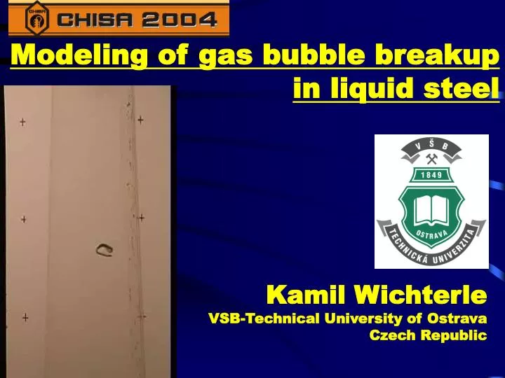
Modeling of gas bubble breakup in liquid steel. K amil Wichterle VSB-Technical University of Ostrava Czech Republic. contents. Gas-liquid contacting in steel metallurgy Bubbles in laboratory and in large-scale Modelling of bubbles in liquid steel Single bubble breakup kinetics

E N D
Modeling of gas bubble breakup in liquid steel Kamil Wichterle VSB-Technical University of Ostrava Czech Republic
contents • Gas-liquid contacting in steel metallurgy • Bubbles in laboratory and in large-scale • Modelling of bubbles in liquid steel • Single bubble breakup kinetics • Cascade of bubble breakup • Sauter diameter decrease
Solid steel Gas – Liquid iron (steel) Cort 1760 puddling Air C+1/2 O2 = CO Liquid iron Fe-C
Gas Liquid iron (steel) Converter 1850 Bessemer (C ) 1860 Thomas, Gilchrist (P,Si) Liquid steel Fe Liquid iron Fe-C Hot air C+1/2 O2 = CO
Gas Liquid iron (steel) Siemens, Martin 1880-1990 Hot air C+1/2 O2 = CO Flue gas C+ CO2 = 2CO Lime CaO, iron ore FeO Liquid iron Fe-C-P-Si-S Liquid steel Fe + slag: CaSiO3, Ca3(PO4)2, CaS
Gas Liquid iron (steel) Durrer 1950 Hot oxygen + lime C+1/2 O2 = CO Liquid iron Fe-C-Si-P-S Pure Fe + slag: CaSiO3, Ca3(PO4)2, CaS
Gases in steel • Diluted gases CO, O, N, H… • Solubility of gases in liquid steel HIGHER than in solid • Solubility of gases in liquid metals INCREASES with increasing temperature • DEGASSING IS ESSENTIAL !
SECONDARY METALLURGY ARGON – VACUUM LADLE • Desorption of diluted gases N, CO, H, O • Sedimentation - floating of slag particles • Addition of alloying metals • De-oxidation • Homogenization TUNDISH • Removing of solid non-metal particles • Homogenization of temperature and composition
Argon –vacuumdegassing vacuum argon
Actual size ARGON –VACUUM TREATMENT • Argon gas-lift for agitation (10-300 W/m3) • Vacuum for desorption of soluble gases (CO, O2, H2, N2) Superficial gas velocity: 0.001 m/s … bottom > 1 m/s … level Atmospheric pressure: 1420 mm Fe RH Ruhrstaal - Heraeus DH Dortmund-Hoerde
Scale problem of rising bubbles • Laboratory – nearly constant bubble volume, short rising time; • Metallurgy - large ferrostatic pressure, vacuum at the level, fast volume changes, moderate rising time; • Deep wells, oceanography - large hydrostatic pressure, slow volume changes, long rising time.
Scale - up • Single bubble shape, bubble rising velocity and bubble breakup depends on: • The bubble volume • Liquid density • Liquid viscosity • Surface tension (and other surface properties) • Gravity acceleration
Dimensionless variables Reynolds, Weber, Eötvös, Morton, Capillary, Laplace, … … numbers Here, three liquid properties μ, ρ, σ, can be everytimes grouped into two variables: μ/ρ (kinematic viscosity) σ/ρ(kinematic surface tension)
density dynamic viscosity kinematic viscosity surface tension Laplace length Laplace velocity liquid Temperature ρ μ ν σ (σ/(ρg))1/2 (σg/ρ)1/4 oC kg/m3 Pas m2/s N/m m m/s moltensteel 1500 7200 5*10-3 0.7*10-6 1.4 4.5*10-3 0.21 water 25 1000 1.0*10-3 1.0*10-6 0.073 2.7*10-3 0.16 mercury 25 13500 1.5*10-3 1.1*10-6 0.46 1.8*10-3 0.14 Wood metal 80 10600 3*10-3 0.3*10-6 0.4 1.9*10-3 0.14 hexane 25 650 0.35*10-3 0.5*10-6 0.018 1.6*10-3 0.13 Similarity of bubbles in liquids
STRATEGY • Experimental study of motion and breakup of bubbles in water under common laboratory conditions • Generalization of the results using dimensional analysis • Introduction of the results into mathematical model of steelmaking process
Overall view drive vacuum thermometer cooling coil rotating blade calming section lamp measuring section rectangular column with conical channel flowmeter mirror syringe system cooler pump
upper projection of the measuring section conical measuring section in a rectangular vessel Mirror Bubble to the camera 100 mm
Detailed view of the measuring section mirror rectangular column PMMA 100×100 mm conical channel Ø 35-65 mm flowmeter BUBBLE front view BUBBLE side view lamp bubble feed syringe bubble injection burette water syringe
Breakup record of levitating bubble Liquid flow
Log scale Time Fraction of non-broken mother bubbles smaller bubbles larger bubbles
Morton Eötvös viscosity Bubble size (R2 = 0,88) Dimensionless half- life Experimental (M=10‑11‑10‑7; Eo =10-20) Θ1/2 = 1.66×10¹⁰Eo-6.05 M-0.04 (R2 = 0,93)
The half-life (in seconds) for air bubbles in water is t1/2 = 0.7 VB-4 (when volume is measured in cubic centimeters). The half-life for gas bubbles in liquid steel should bet1/2 = 410VB-4 (according to dimensional analysis).
Mother bubble Daugthers Grand daughters… Modified dimensionless time (logarithmic) Fraction of bubble generations
This is valid for any case of increasing bubbles : • Hydrostatic pressure decrease • Other ways of external pressure change • Production of bubbles by phase change (boiling, desorption) • Production of bubbles by chemical reactions
Bubble size increases Bubble number increases Bubble breakup No breakup Gas volume increase in hydrostatic column Decreasing pressure Increasing volume
Dimensionless time of breakup of growing bubbles Q = variable gas volume External pressure Hydrostatic pressure bottom Hydrostatic pressure at the moving bubble
Steelmaking Pachuca leaching Laboratory experiments Delay coefficient in bubble breakup Vacuum treatment in metallurgy – some delay
Volume of bubbles after a cascade of breakup Rising velocity Local pressure Bubbles approaching the level:
Conclusions • Size of bubbles rising in a large column can be determined from the developed model using breakup probability data for a single bubble under constant pressure conditions • Average size of bubbles depends on the actual local pressure and rising velocity • Dimensional analysis can be used to estimate the process in liquid metals • Air-water is a better laboratory model of two phase flow in liquid steel than mercury or Wood metal • Further research: The effect of bubble interactions will be considered
Lenka Kulhánková Pavel Raška Jana Wichterlová Marek C. Ruzicka Jiří Drahoš Financial support by the Grant Agency of the Czech Republic (grant No.104/04/0827) is greatly appreciated