Download
1 / 24
240 likes | 341 Vues
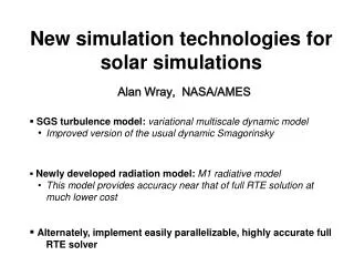
Multiscale simulation Model of Electrical Breakdown. Flyura Djurabekova , Helga Timkó , Aarne Pohjonen , Stefan Parviainen , Juha Samela , Avaz Ruzibaev , Kai Nordlund. Helsinki Institute of Physics and Department of Physics University of Helsinki Finland . CERN, Geneva. Outline.

E N D
Multiscale simulation Model of Electrical Breakdown Flyura Djurabekova,Helga Timkó, AarnePohjonen, Stefan Parviainen, JuhaSamela, AvazRuzibaev, Kai Nordlund Helsinki Institute of Physics and Department of Physics University of Helsinki Finland
CERN, Geneva Outline • Motivation: why do we want to know? • Multiscale model to approach the problem of electrical breakdown • Plasma onset due to the external electric field • Plasma simulation • Surface cratering • Our understanding of electric field effect on metal surface • Summary Accelerator Laborary, Helsinki
Since the stone age sparks and arcs in shape of lightning were around. Frightening the human kind they eventually gave a spark for an evolution. People learned to make use of the sparks… The applications of sparks grew. When the electric field came into play, the short sparks and long maintained arcs could start their inestimable service. But, as in ancient days, we still suffer from lacking the knowledge: Why do we want to know? How does all start?
What is our object? • Main goal: solve the puzzle of electrical breakdown in the CLIC components at rf-fields • Current goal: look closely at “What happens if there is no magnetic component of the field yet?” (Electrostatic approach) • Global goal: find the true mechanisms governing the material response on effect of electrodynamic fields DC setup at CERN for investigating electrical breakdowns
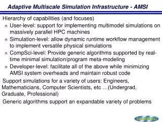
Electrical Breakdown in multiscale modeling approach Stage 1: Charge distribution @ surface Method:DFT with external electric field ~fewfs Stage 2: Atomic motion & evaporation + Joule heating (electron dynamics) Method: Hybrid ED&MD model (includes Laplace and heat equation solutions) P L A S M A O N S E T ~fewns ~ sec/min ~ sec/hours Stage 3a: Onset of tip growth; Dislocation mechanism Method:MD, Molecular Statics… Stage 3b:Evolution of surface morphology due to the given charge distribution Method:Kinetic Monte Carlo Stage 4:Plasma evolution, burning of arc Method:Particle-in-Cell (PIC) ~10s ns ~100s ns Stage 5: Surface damage due to the intense ion bombardment from plasma Method:Arc MD
Stage 1: Charge distribution @ surface Method:DFT with external electric field Stage 1: DFT Method for charge distribution in Cu crystal • Writing the total energy as a functional of the electron density we can obtain the ground state energy by minimizing it • This information will give us the properties we want • Total energy, charge states (as defect energy levels) Energy convergencetest Etot Meshcut-off
+ + + + + + + + Stage 2: Atomic motion & evaporation + Joule heating (electron dynamics) Method: Hybrid ED&MD model (includes Laplace and heat equation solutions) Stage 2: Hybrid ED&MD • Atoms move according Molecular dynamics algorithm, solving Newton equations of motion • But in ED&MD hybrid code for surface atoms as due to the excess or depletion of electron density (atomic charge) • Gauss law is applied to calculate the charges; • Eloc is a solution of Laplace equation Thus, the motion of surface atoms is corrected due to the pulling effect of the electric field fiel
Stage 2: Partial charge induced on the surface atoms by an applied electric field Laplace solver Laplace solution Mo (110) φ=const (conductive material) W (110) T. Ono et al. Surf.Sci., 577,2005, 42
Short tip on Cu (100) surface at the electricfield 10 V nm-1(Temperature 500 K)
Stage 2: Validation of the modelPotential energy of an evaporating atom from adatom position on W (110) We validate our model by the comparison of potential energy of an atom evaporating from the W(110) surface with the DFT calculations from Unlike our model these are static calculations with no account for temperature and dynamic processes
↑E0 Je Emax Je Stage 2: Atomic motion & evaporation + Joule heating (electron dynamics) Method: Hybrid ED&MD model (includes Laplace and heat equation solutions) Stage 2: What about electrons? • At this high electric fields the field emission is non-negligible phenomenon. • Electrons escaping from the surface with the significant current will heat the sharp features on the surface, causing eventually their melting. • The change of the temperature (kinetic energy) due to the Joule heating and heat conduction calculated by 1D heat equation Moredetails at Posterby Stefan Parviainen
+ + + + + + + + Stresses due to the field • While making the simulation of the atomic motion under an electric field (high values) we notice the significant expansion of the surface. This observation led us to think on the effect of the pressure. The pressure can be not only due to the applied filed, but also of a different nature. However, redistribution of any present stresses may be caused by the field → Fel STRESS =0E2/Y
Stage 3a: Onset of tip growth; Dislocation mechanism Method:MD, Molecular Statics… Step 3a: Are tiny whiskers possible? • There is a number of mechanisms which might make the dislocations move coherently causing a directed mass transport, thus forming a whisker growth. We are looking for the most probable at our condition. Talk by AarnePohjonen in the afternoon
Is itonlycohesiveenergywecansee a correlationwith? • The dislocation motion is strongly bound to the atomic structure of metals. In FCC (face-centered cubic) the dislocations are the most mobile and HCP (hexagonal close-packed) are the hardest for dislocation mobility.
Stage 3b:Evolution of surface morphology due to the given charge distribution Method:Kinetic Monte Carlo Step 3b: Kinetic simulation of surface diffusion under the electric field • We initiate new activity to simulate long term processes (surface diffusion, electromigration) • Energy barriers calculated by ED&MD simulation will be introduced into KMC code to assess the probability of the atom/defect cluster jumps • Time is calculated according to the residence-time algorithm V
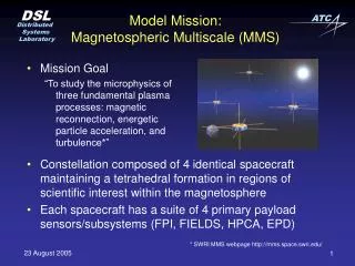
Stage 4:Plasma evolution, burning of arc Method:Particle-in-Cell (PIC) Stage 4: plasma formation and evolution ~ 4-6 kV • 1d3v electrostatic PIC-MCC code developed for plasma simulations • Resolving the main stream of plasma • Areal densities of physical quantities • To have a direct comparison with experiments, we adjusted simulation parameters to the DC setup at CERN r=1 mm d=20 μm Cu Next talk by Helga Timko
Stage 5: Surface damage due to the intense ion bombardment from plasma Method:Arc MD Step 5: Huge fluxes (1024 ion cm-2 sec-1) of accelerated ions cause severe surface damage Ion fluxes leave rims of peculiar shape
Cu (100) bombarded by DC arc ions: Φ = 5.66x1024 cm-2 sec-1, E ≃ 8 keV • MD simulations of surface bombardment on a given area A • Ion flux and energy distribution corresponded exactly to that from PIC simulations! • Flux of ~1025 on eg. r=15 nm circle => one ion/20 fs!!
Comparative simulation of arc ion bombardment and thermal deposition of energy (no ions) PIC energy distribution Thermal heating only
Step 5: Plasma-surface interactionCrater formation The comparison of simulated and experimental craters is encouraging (scaling law is necessary at the moment) • [H. Timko, F. Djurabekova, L. Costelle, K. Nordlund, K. Matyash, R. Schneider, A. Toerklep, G. Arnau-Izquierdo, A. Descoeudres, S. Calatroni, M. Taborelli, and W. Wuensch, Phys. Rev. B (2010), accepted
Craterprofiles: Moclusterbombardment E = 8 keV/atom N = 1000 N = 100 zoomed200% Macroscopic saturation level N = 5000
Summary • Multiscale modeling gives clear insight to the ongoing processes on the surface at high electric fields • We suggest a probable scenario of triggering of a tip growth: Voids may serve as efficient source of dislocations for the mass transport to the surfaces! • Modeling of DC electrical breakdown can shed the light on the metal surface response to the electrical field effect also in case of rf electrical breakdown • Simulation of craters created by formed plasma reveals the dependence between energy deposition and crater shape.