Download

1 / 13
140 likes | 368 Vues
TOOLING. WHAT IS REQUIRED OF THE TOOL?. support weight of the part maintain structural integrity and dimensional stability following multiple heating and cooling cycles sustain handling loads able to achieve a specified temperature at a specified rate accommodate fabrication process.

E N D
WHAT IS REQUIRED OF THE TOOL? • support weight of the part • maintain structural integrity and dimensional stability following multiple heating and cooling cycles • sustain handling loads • able to achieve a specified temperature at a specified rate • accommodate fabrication process
DECISIONS REGARDING THE TOOLING • male or female - which face of part should be tool surface • tooling materials • wood • plaster • foam • polyurethane, silicone, latex • salt/sand (single use) • metal • composite • issues driving the selection of tooling material • life (number of cycles) • cost • nonrecurring - machinability (aluminum easier to machine than steel) • recurring - ease of repair • heat transfer capability • heat up and cool down times • ability to control tool temperature • thermal characteristics of tooling materials
“HARD” TOOLING VS “SOFT” TOOLING • hard tooling • many cycles • high cost • soft tooling • few cycles • difficult to maintain tight tolerances • low cost
THERMAL EXPANSION MUST BE ACCOUNTED FOR IN THE DESIGN OF TOOLING • prior to gel, “wet” part and tool expand together • at certain time/temperature part gels • tool and part expand at own rate depending on respective CTEs • cool down at respective CTEs • thermal stresses can be introduced • difficulty extracting tool • dimensioning tool to account for the different CTEs and change in temperature • tolerances on tooling typically ¼ tolerances on part
TOOLING DESIGN EXAMPLE • Design the tooling (material and dimensions) to produce each of the two C-channel designs defined below. The program requires production of 5,000 C-channels of each design. A smaller C-channel is bonded to the inside flanges of the C-channels shown below to form a box beam configuration. The C-channels are fabricated with a graphite/epoxy system. The C-channels are cured in an autoclave at 350°F, 100 psi. • design #1: [±50°]s, CTE (90° direction) = -0.2893 x 10⁻⁶ in/in/°F • design #2: [±25°]s, CTE (90° direction) = 9.4869 x 10⁻⁶ in/in/°F • C-channel sketch
METAL TOOLING • machined • electroforming (typically nickel, 0.125 in thick) • fiberglass plating mandrel placed in nickel solution • thickness build up 0.0005 in - 0.001 in/hr
COMPOSITE TOOLING • good match between tooling CTE and part CTE • lightweight - reduces handling costs • lower cost • limited life in comparison with metal tools
FABRICATION OF COMPOSITE TOOLING • female tool (model (plug) - splash - master - tool) • model - wood, plaster, ... • splash - room temp cure (low cost E-glass) • master (transfer tool) - room temp cure/high service temp resin • tool - high cure/service temp resin (temp capability > part cure temp) • male tool (model - master - tool) • lay-up • isotropic (0°/±45°/90°)s • lightweight fabrics against gel coat (will not print through), medium fabrics next, heavy weight fabrics to build up thickness • face sheet - reinforcing ribs - base (egg crate) • substructure should be of similar materials to minimize thermal stresses due to CTE mismatch • minimize effect of substructure to create thermal gradients through face sheet
METAL-COATED COMPOSITE TOOLING • combine advantages of metal and composite • metal • long life • excellent mold surface finish • faster heat up times • ease of repair • composite • lightweight • lower cost • ease in producing large molds • methods of fabricating • plate composite tool with metal by electrolytic or chemical plating • plate or thermal spray metal on master, then fabricate composite tool over metal surface
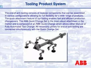
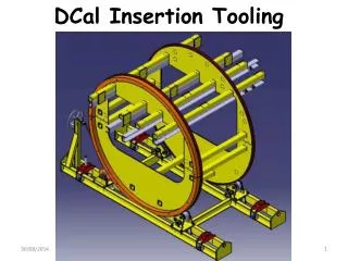
OTHER TYPES OF TOOLING • segmented tools (mandrels) to prevent “trapped” tooling • elastomeric (silicone rubber) tooling • trapped rubber molding • used in areas with special pressure needs (pressure intensifiers) • internal bladder/female mold • integral tooling • caul plates • distribute applied pressure evenly over part • maintain heat transfer similar to tool side • ply locating templates
EXTRACTING THE TOOLING • tool should be designed to facilitate extraction • taper • take advantage of CTE mismatch • jacking points • grapple points • blow holes
PROTOTYPE TOOLING • composite tool • subwoofer part 1, part 2 • aircraft cowling (using foam plug) • polyurethane, silicone tool (Freeman Mfg videos) • latex tool