Download
1 / 22
220 likes | 224 Vues
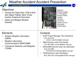
This report discusses the flight testing of the FAA/NASA weather information communications system using VDL Mode 3 broadcast service. The effectiveness of using VDL Mode 3 as a digital data link for transmitting weather information to aircraft is validated. Integration between the NASA Glenn Ground Server, Rockwell Collins VDL Mode 3 avionics suite, and the FAA VDL Mode 3 Ground System is demonstrated.

E N D
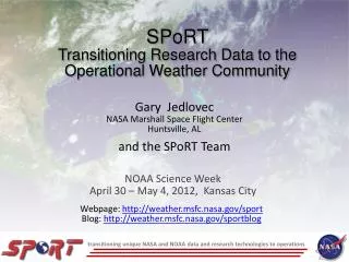
AERONAUTICAL COMMUNICATIONS PANEL (ACP) WORKING GROUP M-10 Montreal, Canada 23 – 26 May 2005 FAA/NASA Weather Information Communications Flight Testing Via VDL Mode 3 Broadcast Service Presented By: Peter Muraca FAA Technical Center Atlantic City, NJ USA
Background • Air / Ground Weather Information System flight testing was conducted between the FAA, NASA Glenn, and Rockwell Collins at the FAA Technical Center on April 11 - 13, 2005. Weather products were transmitted via the VDL Mode 3 Subnetwork [report available mid-June 05’]. • Laboratory Testing (over RF) Conducted March 7 - 10, 2005[report available] • Laboratory Testing (attenuated antennas) Conducted November 15 - 18, 2004[report available] • Validate the effectiveness of using the VHF Digital Link (VDL) Mode 3 broadcast communications technology as a digital data link to transmit weather information to the aircraft. • Demonstrate integration between the NASA Glenn Ground Server, Rockwell Collins VDL Mode 3 avionics suite, and the FAA VDL Mode 3 Ground System for this work effort. • Utilize the VDL Mode 3 Broadcast service as specified in RTCA DO-224b (MASPS) and ICAO Doc 9805. Objective
NASA Glenn - Components • Data Logger • Ground Server • TCP/IP client/server • UDP/IP client/server • Weather Product Generator
Rockwell Collins - Components • VHF Digital Radio (VDR) – VHF-2100 • Communications Management Unit • (CMU-900) • Gables Radio Tuning Panel (RTP) • Multifunction Control Display Unit (MCDU)
FAA - Components • Radio Interface Unit (RIU) • Real Time Platform (RTPF) • Voice Channel Module (Vocoder for each of 4 TDMA timeslots) • Multimode Digital Radio (MDR) Transmitter & Receiver • Channel Simulator (RF Attenuated Circuit) • Ground Network Interface (GNI) • IP Connection to NASA GRC
Results to Date • Weather products were successfully broadcasted from the WINCOMM ground server via the VDL Mode 3 ground station and displayed on the Rockwell Collins Avionics, such products included: • Metars • Graphical Precipitation Maps • Depiction Maps • Icing Maps • Winds Maps • Turbulence • VDL Mode 3 simultaneous voice and data was successfully conducted. • WINCOMM weather products were successfully broadcasted continuously, during five-minute increments, for Subnetwork load tests. • Larger file size (26,000 bytes) weather products were broadcasted from the WINCOMM ground server to test data capacity (data limit, transmission reliability, and assembly of product on the avionics). File transfers were successful. 1k product transmission = 1.2 seconds 3k product transmission = 4.0 seconds 26k transmission product = 55 seconds
Products – Uplink Broadcast via VDL Mode 3 Depiction Weather Product
Products – Uplink Broadcast via VDL Mode 3 Nexrad Weather Product
Products – Uplink Broadcast via VDL Mode 3 Icing Weather Product
Products – Uplink Broadcast via VDL Mode 3 Metar Weather Product
Products – Uplink Broadcast via VDL Mode 3 Winds Weather Product
Products – Request / Reply via VDL Mode 3 Turbulence Weather Product
Observers and Participants Representation • FAA Technical Center • NASA Glenn Research Center • Rockwell Collins • FAA Flight Safety • FAA Aircraft Certification • Electronic Navigation Research Institute (ENRI) [Japan] • FAA Program Office
Backup Slide 1VDL Mode 3 Ground Station functioned as the link between the airborne segment and the WINCOMM ground server and all transmissions were attenuated via the channel simulator. The GNI interface provided a gateway to the NASA Glenn Weather Server. The GNI also provided a user interface in which to control multiple RIU protocol engines. Internet Protocol (IP) gateway was added to the WJHTC ground system GNI that allowed for two data services including a broadcast service and a point-to-point request/reply link to the airborne segment. The IP protocol provided network connectivity between the GRC Server, GNI and Airborne Segment.User Datagram Protocol (UDP) was used to transfer unicast datagrams from the GRC ground server to the Airborne segment. (The GNI gateway decoded the IP protocol fields to determine if UDP was signaled). The Transmission Control Protocol (TCP) was used to support a request and reply service from the airborne segment to the WINCOMM ground server. (The GNI gateway decoded the IP protocol fields to determine if TCP was signaled and sent appropriate signals to the RIU protocol engine for further actions).
Backup Slide 2 • WINCOMM Server, GNI, and RIU are physically connected to a hub via Ethernet cabling • Socket connection (TCP/IP) between GNI and WINCOMM server (port 5001) for message throttle control • GNI receives flow control data from the MDR via the RIU • GNI configures Ethernet port for promiscuous mode which allows all Network Layer traffic to be visible • An Ethernet packet socket configured for IP frames is opened and a “bind” is performed with the Ethernet port • This allows GNI to “sniff” for any IP packet (TCP or UDP) with the WINCOMM Server as the source address and the Aircraft as the destination • IP frames are not effected • This is important since we rely on the IP Network Layer to segment any messages that are too large for VDL Mode 3 (> 922 Bytes) and then reconstruct them at the destination address • GNI routes the IP packets to the appropriate RIU • GNI opens a TCP/IP socket (server) with the RIU (client) • IP packets destined for the Aircraft are sent across this connection as the datagram payload of the TCP packets • RIU IP Layer removes TCP header • This leaves the IP packet datagrams destined for Aircraft • RIU adds DLS framing to the IP packet datagrams • RIU interfaces with the VDL Mode 3 MDR over a high speed serial link • Message is sent over this connection to the MDR • VDL Mode 3 MDR transmits data
Backup Slide 3 • VDL Mode 3 MDR -> RIU -> GNI -> WINCOMM Server • VDL Mode 3 MDR receives data • VDL Mode 3 MDR interfaces with the RIU over a high speed serial link • Message destined for the WINCOMM Server is sent over this connection • RIU removes DLS framing • RIU – GNI TCP/IP socket • IP packets destined for the WINCOMM Server are sent across this connection as the payload of the TCP packets • GNI IP Layer removes TCP header • This leaves the IP packet datagrams destined for the WINCOMM Server • GNI opens a RAW socket configured to include an IP header • This allows GNI to send the IP packets to the Ethernet port and not alter the IP header • GNI IP Layer directs packets to the WINCOMM Server • All weather PDUs are sent from the WINCOMM Server as UDP datagrams. • All weather PDU requests and turbulence test messages are sent to the WINCOMM Server from the Aircraft as TCP datagrams. • The WINCOMM Server replies with a simple TCP “ack”
Backup Slide 4 • Turbulence data is generated from on-board avionics sensors, in this test flight, the data was generated via on-board computer. • Data collected is sent to the NASA ground server via TCP/IP over VDL Mode 3 subnet • Ground server composes graphical Turbulence graphical product and delivers it to the GNI for broadcast to aircraft • VDL Mode 3 Broadcast System implemented and tested