Download
1 / 18
230 likes | 506 Vues
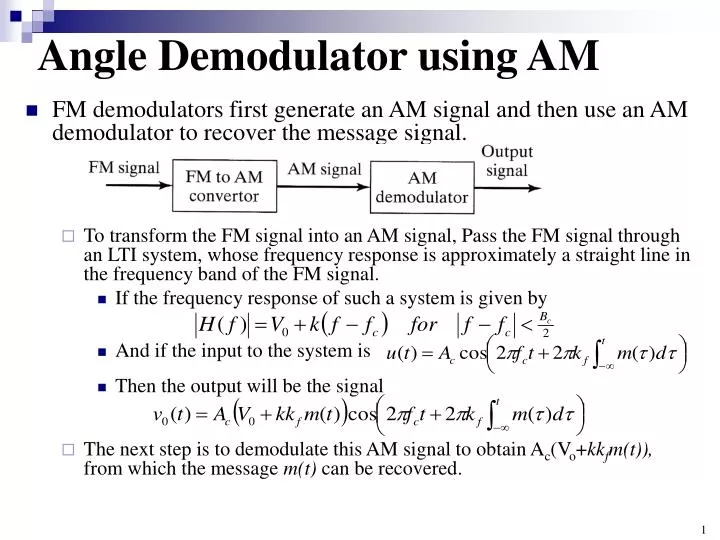
Angle Demodulator using AM. FM demodulators first generate an AM signal and then use an AM demodulator to recover the message signal.

E N D
Angle Demodulator using AM • FM demodulators first generate an AM signal and then use an AM demodulator to recover the message signal. • To transform the FM signal into an AM signal, Pass the FM signal through an LTI system, whose frequency response is approximately a straight line in the frequency band of the FM signal. • If the frequency response of such a system is given by • And if the input to the system is • Then the output will be the signal • The next step is to demodulate this AM signal to obtain Ac(Vo+kkfm(t)), from which the message m(t) can be recovered.
Angle Demodulators using AM • Many circuits can be used to implement the first stage of an FM demodulator, i.e., FM to AM conversion. • One candidate is a simple differentiator with • Another candidate is the rising half of the frequency characteristics of a tuned circuit, as shown in below • Such a circuit can be easily implemented, but usually the linear region of the frequency characteristic may not be wide enough. • To obtain linear characteristics over a wide range of frequencies, usually two circuits tuned at two frequencies f1and f2are connected in a configuration, which is known as a balanced discriminator.
Angle Demodulator using AM A balanced discriminator and the corresponding frequency response.
Angle Demodulator using PLL • A different approach to FM-signal demodulation is to use a phase-locked loop (PLL) => PLL-FM demodulator • The input to the PLL is the angle-modulated signal (where, for FM, ) • The VCO generates a sinusoid of a fixed frequency; in this case, it generates the carrier frequency fc, in the absence of an input control voltage.
Angle Demodulator using PLL • Now, suppose that the control voltage to the VCO is the loop filter's output, denoted as v(t). • Then, the instantaneous frequency of the VCO is • where kvis a deviation constant • Consequently, the VCO output may be expressed as • where • The phase comparator is a multiplier and a filter that rejects the signal component centered at 2fc. • Hence, its output may be expressed as • where the difference (t) -v(t)e(t) constitutes the phase error. • The signal e(t) is the input to the loop filter.
Angle Demodulators using PLL • Let us assume that the PLL is in lock position, so the phase error is small. • Then, • under this condition, so we may deal with the linearized model of the PLL, shown in below • We may express the phase error as • Or equivalently, either as • Or as (Eq. 1) Linearized PLL:
Angle Demodulators using PLL • The Fourier transform of (Eq. 1) is • Hence (Eq.2) • Now, suppose that we design G(f) such that • Then, from (Eq.2), • Or equivalently, • Since the control voltage of the VCO is proportional to the message signal, v(t) is the demodulated signal.
FM-Radio Broadcasting • Commercial FM-radio broadcasting utilizes the frequency band 88-108 MHz for the transmission of voice and music signals. • The carrier frequencies are separated by 200 kHz and the peak frequency deviation is fixed at 75 kHz. • Preemphasis is generally used, as described in Chapter 6, to improve the demodulator performance in the presence of noise in the received signal. • The receiver most commonly used in FM-radio broadcast is a superheterodyne type. • The block diagram of such a receiver is shown in below
FM-Radio Broadcasting Block diagram of a superheterodyne FM-radio receiver.
FM-Radio Broadcasting • As in AM-radio reception, common tuning between the RF amplifier and the local oscillator allows the mixer to bring all FM-radio signals to a common IF bandwidth of 200 kHz, centered at fIF= 10.7 MHz. • Since the message signal m(t) is embedded in the frequency of the carrier, any amplitude variations in the received signal are a result of additive noise and interference. • The amplitude limiter removes any amplitude variations in the received signal at the output of the IF amplifier by bandlimiting the signal. • A bandpass filter, which is centered at fIF= 10.7 MHz with a bandwidth of 200 kHz, is included in the limiter to remove higher-order frequency components introduced by the nonlinearity inherent in the hard limiter.
FM-Radio Broadcasting • A balanced frequency discriminator is used for frequency demodulation. • The resulting message signal is then passed to the audio-frequency amplifier, which performs the functions of deemphasis and amplification. • The output of the audio amplifier is further filtered by a lowpass filter to remove out-of-band noise, and this output is used to drive a loudspeaker.
FM-Stereo Broadcasting <Transmitter> • Many FM-radio stations transmit music programs in stereo by using the outputs of two microphones FM-stereo transmitter and signal spacing.
FM-Stereo Broadcasting • The signals from the left and right microphones, ml(t) and mr(t), are added and subtracted . • The sum signal ml(t)+mr(t) is left unchanged and occupies the frequency band 0-15 kHz. • The difference signal ml(t)-mr(t) is used to AM modulate (DSB-SC) a 38 kHz carrier that is generated from a 19-kHz oscillator. • A pilot tone at the frequency of 19 kHz is added to the signal for the purpose of demodulating the DSB-SC AM signal. • We place the pilot tone at 19 kHz instead of 38 kHz because the pilot is more easily separated from the composite signal at the receiver. • The combined signal is used to frequency modulate a carrier.
FM-Stereo Broadcasting • By configuring the baseband signal as an FDM signal, a monophonic FM receiver can recover the sum signal ml(t)+mr(t) by using a conventional FM demodulator. • Hence, FM-stereo broadcasting is compatible with conventional FM. • In addition, the resulting FM signal does not exceed the allocated 200-kHz bandwidth. <Receiver> • The FM demodulator for FM stereo is basically the same as a conventional FM demodulator down to limiter/discriminator. • Thus, the received signal is converted to baseband. • Following the discriminator, the baseband message signal is separated into the two signals, ml(t)+mr(t)and ml(t)-mr(t), and passed through deemphasis filters, as shown in Figure 4.18.
FM-Stereo Broadcasting • The difference signal is obtained from the DSB-SC signal via a synchronous demodulator using the pilot tone. • By taking the sum and difference of the two composite signals, we recover the two signals, ml(t) and mr(t). • These audio signals are amplified by audio-band amplifiers, and the two outputs drive dual loudspeakers. • As indicated, an FM receiver that is not configured to receive the FM stereo sees only the baseband signal ml(t)+mr(t)in the frequency range 0-15 kHz. • Thus, it produces a monophonic output signal that consists of the sum of the signals at the two microphones.
FM-Stereo Broadcasting Figure 4.18 FM-stereo receiver.
Television Broadcasting • Commercial TV broadcasting began as black-and-white picture transmission in London in 1936 by the British Broadcasting Corporation (BBC). • Color TV was demonstrated a few years later, but commercial TV stations were slow to develop the transmission of color-TV signals. • This was due to the high cost of color-TV receivers. • With the development of the transistor, the cost of color TV decreased significantly. • By the middle 1960s, color TV broadcasting was widely used by the industry. • The frequencies allocated for TV broadcasting fall in the VHF and UHF bands. • Table 4.2 lists the TV channels allocated in the United States. • The channel bandwidth allocated for the transmission of TV signals is 6 MHz. • In contrast to radio broadcasting, standards for television-signal transmission vary from country to country. • The US standard was set by the National Television Systems Committee (NTSC).