Download
1 / 51
510 likes | 679 Vues
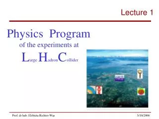
Physics Program of the experiments at L arge H adron C ollider. Lecture 2. Outline of this lecture. What is general purpose detector? ATLAS detector: Magnet System Inner Detector Calorimetry Muon Spectrometer Trigger

E N D
Physics Program of the experiments at Large HadronCollider Lecture 2
Outline of this lecture What is general purpose detector? ATLAS detector: Magnet System Inner Detector Calorimetry Muon Spectrometer Trigger ATLAS detector test beam 2004
General Purpose Detectors When it became more and more likely, early in 1980, that an electron–positron collider, energetic enough to produce the as yet undiscovered Z boson, would be constructed at CERN, some of us got together to initiate discussions on a possible experiment. Some of us who collaborated in the CDHS neutrino experiment were joined by colleagues from Orsay, Pisa, Munich (Max Planck) and Rutherford Labs. The first question we asked ourselves was: ‘Can we think of a focused experiment, requiring a specialized rather than general-purpose detector?’ The answer was a clear no, and in fact, no special purpose detector was ever built at LEP. So we started to think of a general-purpose, 4π detector, such as had been developed at the DESY Petra and the SLAC PEP colliders, but clearly more ambitious in all aspects: tracking resolution, angular coverage, calorimetry, and particle identification. Jack Steinberger – Nobel Laureate and first spokesman of the Aleph Experiment
General Principle Collider detectors look all similar since they must perform in sequence the same basic measurements. The dimension of the detector are driven by the required resolution . The calorimeter thickness change only with the logarithm of the energy: for this reason the dimension of the detectors change only slightly with the energy.
General purpose detector • Identification … • for event selection • For both, need different stages: • Inner tracker • Calorimeters • Muon system(trigger andprecisionchambers) • … and measurement • for event reconstruction.
n µ Muon chambers g Hadronic calorimeter e n Electromagnetic calorimeter p Inner tracker Particle identification
Particle measurement • Detectors must be capable of • Resolving individual tracks, in-and-outside the calorimeters • Measuring energy depositions of isolated particles and jets • Measuring the vertex position. • Detector size and granularity is dictated by … the required (physics) accuracy … the particle multiplicity. • Size + granularity determine … the no. of measuring elements … i.e. the no. of electronics channels.
The ATLAS Detector Length : 40 m Radius : 10 m Weight : 7000 tons Electronics channels : 108
Basic design criteria • Very good electromagnetic calorimetry for electron and photon identification and measurements, complemented by full-coverage hadronic calorimetry for accurate jet and missing transverse energy (ETmiss) measurements. • High precision muon momentum measurements, with capability to guarantee accurate measurements at the highest luminosity using the external muon spectrometer alone. • Efficient tracking the high luminosity for high-pT-lepton-momentum measurements, electron and photon identification, t-lepton and heavy-flavour identification, and full event reconstruction capability at lower luminosity. • Large acceptance in pseudorapidity (h) with almost full azimuthal angle (f) coverage everywhere. The azimuthal angle is measured around the beam axis, whereas pseudorapidity relates to the polar angle () where is the angle from • Triggering and measurements of particles at low-pT thresholds, providing high efficiencies for most physics processes of interest
Basic design criteria • Lepton measurement: pT GeV 5 TeV • ( b lX, W’/Z’) • Mass resolution (m ~ 100 GeV) : • 1 % (H gg, 4l) • 10 % (W jj, H bb) • Calorimeter coverage : || < 5 • (ETmiss, forward jet tag for strongly interacting Higgs) • Particle identification : • eb 50 % Rj 100 (H bb, SUSY) • et 50 % Rj 100 (A/H tt) • eg 80 % Rj > 103 (H gg) • ee> 50 % Rj > 105 e/jet ~ 10-3s = 2 TeV e/jet ~ 10-5 s = 14 TeV
Basic design criteria In addition : 3 crucial parameters for precision measurements • Absolute luminosity : goal < 5% • Main tools: machine, optical theorem, rate of • known processes (W, Z, QED pp pp ll) • EM energy scale : goal 1‰ most cases • 0.2‰ W mass • Main tool: Z ll (1 event / 1 /s at low L) • close to mW, mh • N.B.: 1‰ achieved by CDF/D0 (despite small Z sample) • Jet energy scale: goal 1% (mtop, SUSY) • (limited by physics) • Main tools : Z + 1 jet (Z ll) • W jj from top decays • (10-1 events/s low L) • N.B. 4% at Tevatron e/jet ~ 10-3s = 2 TeV e/jet ~ 10-5 s = 14 TeV Requirements: tracker material to 1%, overall alignment to 0.1 mm, overall B-field to 0.1‰, muon E-loss in calorimeters to 0.25%, etc.
The ATLAS Magnet System Fe yoke (calorimeter) 3 superconducting air core toroids Barrel toroid Central Solenoid superconducting solenoid End-cap toroid • 26m long, 20m outer diameter 1350 tons
The ATLAS Magnet System The magnet configuration is based on an inner thin superconducting solenoid surrounding the inner detector cavity, and large superconducting air-core toroids consisting of independent coils arranged with an eight-fold symmetry outside the calorimeters. The solenoid provides a central magnetic field of 2T (peak at 2.6T). The peak magnetic field of barrel toroid is 3.9T and of end-cap toroid is 4.1T. The solenoid has been inserted into the LAr cryostat at the end of February 2004, and it was tested at full current (8 kA) during July 2004 • length of 5.3m and diameter of 2.4m • 5.7 tons
Toroid system Barrel Toroid parameters 25.3 m length 20.1 m outer diameter 8 coils 1.08 GJ stored energy 370 tons cold mass 830 tons weight 4 T on superconductor 56 km Al/NbTi/Cu conductor 20.5 kA nominal current 4.7 K working point End-Cap Toroid parameters 5.0 m axial length 10.7 m outer diameter 2x8 coils 2x0.25 GJ stored energy 2x160 tons cold mass 2x240 tons weight 4 T on superconductor 2x13 km Al/NbTi/Cu conductor 20.5 kA nominal current 4.7 K working point Barrel Toroid: 8 separate coils End-Cap Toroid: 8 coils in a common cryostat The ATLAS Magnet System
The ATLAS Magnet System Barrel Toroid coil transport and installation
The ATLAS Magnet System • Magnetic field calculation • Impact of coils & magnetic material positions
Inner Detector The Inner Detector (ID) is organized into four sub-systems: Pixels (0.8 108 channels) Silicon Tracker (SCT) (6 106 channels) Transition Radiation Tracker (TRT) (4 105 channels) Common ID items
Inner Detector The Inner Detector (ID) is contained within a cylinder of length 7m and a radius of 1.15m, in a solenoidal field of 2T. Pattern recognition, momentum and vertex measurements, and electron identification are achieved with a combination of discrete high-resolution semiconductor pixel and strip detectors in the inner part of the tracking volume, and continous straw-tube tracking detectors with transition capability in its outer part.
Inner Detector First completed disk (two layers of 24 modules each, with 2’200’000 channels of electronics First complete SCT barrel cylinder TRT barrel support with all modules
Inner Detector total weights • PIXEL volume 78 kg Rmean 15cm • SCT volume 345 kg Rmean 38cm • TRT volume(no C-wheels) 1960 kg Rmean 86cm • Services volume 2500 kg • Total ID 4880 kg GeoModel services breakdown TRT services 2150 kgSCT services 292 kgPixel services 68 kg Required understanding material description to better than 1%
Tile barrel Tile extended barrel LAr hadronic end-cap (HEC) LAr EM end-cap (EMEC) LAr EM barrel LAr forward calorimeter (FCAL) Calorimetry
Calorimetry Had Tiles Highly granular liquid-argon (LAr) electromagnetic (EM) sampling calorimetry, with excellent performance in terms of energy and position resolution, covers the pseudorapidity range |h| < 3.2. In the end-caps, the LAr technology is also used for the hadronic calorimeters, which share the cryostats with the EM endcaps. The same cryostats also house the special LAr forward calorimeters which extend the pseudorapidity coverage to |h| < 4.9. The bulk of the hadronic calorimetry is provided by a novel scintillator-tile calorimeter, which is separated into large barrel and two smaller extended barrel cylinders, one on each side of the barrel. The overall calorimeter system provides the very good jet and ETmiss performance of the detector. Had LAr EM LAr Solenoid Forward LAr Barrel cryostat
Calorimetry LAr barrel EM calorimeter after insertion into the cryostat Solenoid just before insertion into the cryostat
Muon Spectrometer System Precision chambers: - MDTs in the barrel and end-caps - CSCs at large rapidity for the innermost end-cap stations Trigger chambers: - RPCs in the barrel - TGCs in the end-caps The Muon Spectrometer is instrumented with precision chambers and fast trigger chambers A crucial component to reach the required accuracy is the sophisticated alignment measurement and monitoring system
Muon Spectrometer System The calorimeter is surrounded by the muon spectrometer. The air-core toroid system, with a long barrel and two inserted end-cap magnets, generates a large magnetic field volume with strong bending power within a light and open structure. Multiple-scattering effect are minimised, and excellent muon momentum resolution is achieved with three stations of high-precision tracking chambers. The muon instrumentation also included as a key component trigger chambers with fast time response.
The installation of the barrel muon station has started in the feet region of the detector as well as within the third BT
ATLAS detector in G4 simulation Jaka jest skala problemu? • 25,5 millionów oddzielnych elementów • 23 000różnych obiektów geometrycznych • 4673różnych typów geometrycznych • kontrolowanie nakładających się na siebie przypadków • 1 000 000sygnałów w detektorze na przypadek
22 m Weight: 7000 t 44 m • Interactions every 25 ns … • In 25 ns particles travel 7.5 m Trigger The ATLAS experiment • Cable length ~100 meters … • In 25 ns signals travel 5 m
Event rates • N = no. events / sec • L = luminosity = 1034 cm-2 s-1 • inel= inel. cross-section = 70 mb • E = no. events / bunch xing • Dt= bunch spacing = 25 ns • N = L x inel= 1034 cm-2 s-1 x 7 10-26 cm2 = 7 108 Hz • E = N / Dt= 7 108 s-1 x 25 10-9 s = 17.5 (not all bunches are filled) = 17.5 x 3564 / 2835 = 22 events / bunch xing The LHC produces 22 overlapping p-p interactions every 25 ns
… still much more complex than a LEP event Particle multiplicity • h = rapidity = log(tg/2) (longitudinal dimension) • uch = no. charged particles / unit-h • nch = no. charged particles / interaction • Nch = no. chrgd particles / bunch xing • Ntot = no. particles / bunch xing • nch= uch x h= 6x 7 = 42 • Nch= nch x 22 = ~ 900 • Ntot= Nch x 1.5 = ~ 1400 The LHC flushes each detector with ~1400 particles every 25 ns
Cross-section Orders of magnitude amongst x-sections of various physics channels: • Inelastic : 109 Hz • W -> ln : 102 Hz • t-t production : 101 Hz • Higgs (m=100 GeV/c2) : 10-1 Hz • Higgs (m=600 GeV/c2) : 10-2 Hz ==> selection power : 1010-11 … lepton decay BR : ~ 10-2 ==> Selection power for Higgs discovery : 1013
~ 100 Hz Physics ~ 100 MB/s ARCHITECTURE Trigger DAQ 40 MHz 10’s PB/s(equivalent) Three logical levels Hierarchical data-flow LVL1 - Fastest:Only Calo and MuHardwired On-detector electronics: Pipelines ~3 ms LVL2 - Local:LVL1 refinement +track association Event fragments buffered in parallel ~ ms LVL3 - Full event:“Offline” analysis Full event in processor farm ~ sec.
ARCHITECTURE Trigger DAQ 40 MHz 10s PB/s(equivalent) Level-1 Pipelines ~3 ms 100 kHz 100 GB/s ~ ms Level-2 Buffers ~ kHz ~ GB/s Event Filter Processor Event Filter ~ sec. Recording ~ 100 Hz Physics ~ 100 MB/s
n - e e q µ + - c 1 µ - ~ q q Z ~ p g H p p p ~ q Z + m µ + - q ~ m c 0 µ 2 - ~ c 0 1 Physics and Trigger High pT Physics Production of heavy objects may be detected via one or more of the following signatures: One or more isolated, high-pT charged leptons Large missing ET (from neutrinos, dark matter candidates) High multiplicity of large pT jets Isolated high-pT photons Copious b production relative to QCD
Physics and Trigger H(130 GeV) Z0Z0*+-e+e- Minimum Bias
Higgs → ZZ → 2e+2m Looking for interesting event 23 min bias events
Inclusive Selection Signatures Inclusive Selection Signatures • To select an extremely broad spectrum of “expected” and “unexpected” Physics signals (hopefully!). • The selection of Physics signals requires the identification of objects • that can be distinguishedfrom the high particle density environment. also inclusive missingET, SumET, SumET_jet & many prescaled and mixed triggers The list must be non-biasing,flexible, include some redundancy, extendable, to account for the “unexpected”.
2 2e Region of Interest (RoI) Mechanism Hardware • LVL1 triggers on high pT objects • calorimeter cells and muon chambers • to find e/g,t,jet,m candidates • above thresholds • identifies Regions of Interest • fixed latency 2.5 ms Software • LVL2 uses Regions of Interest • local data access, reconstruction & analysis • sub-detector matching of RoI data • produces LVL2 result • average latency~10 ms Software • Event Filter • can be “seeded” by LVL2 result • potential full event access, • offline-like Algorithms O(1 s) latency H →2e + 2
Inner Detector Channels Fragment size - kB Muon Spectrometer Channels Fragment size - kB Pixels 1.4x10⁸ 60 MDT 3.7x10⁵ 154 SCT 6.2x10⁶ 110 CSC 6.7x10⁴ 256 TRT 3.7x10⁵ 307 RPC 3.5x10⁵ 12 TGC 4.4x10⁵ 6 Calorimetry Channels Fragment size - kB Trigger Channels Fragment size - kB LAr 1.8x10⁵ 576 LVL1 (calo) ~104 28 Tile 104 48 ATLAS Event Size At 40 MHz: 1 PB/sec affordable mass storage b/w: 300 MB/sec ☛ 3 PB/yearfor offline analysis ☛ ~ 200 Hz Trigger Rate ATLAS event size: 1.5 Mbytes140 million channelsorganized into ~1600 Readout Links
ATLAS Three Level Trigger Architecture • LVL1 decision made with calorimeter data with relatively coarse granularity and muon trigger chambers data. • Buffering on detector • LVL2 uses Region of Interest data (ca. 2%) with full granularity combines information from all detectors performs fast rejection. • Buffering in ROBs • EventFilter refines the selection can perform event reconstruction at full granularity using latest alignment and calibration data. • Buffering in EB & EF hardware 2.5 ms software ~10 ms ~2 kHz ~200 Hz ~ sec.
LVL1 - Muons & Calorimetry e/ trigger Toroid Muon Trigger looking for coincidences in muon trigger chambers 3 out of 4 (low-pT; >6 GeV) and 3 out of 4 + 1/2 (Barrel) or 2/3 (Endcap) (high-pT; > 20 GeV) Trigger efficiency 91% (low-pT) and 87% (high-pT) Calorimetry Trigger looking for e/g, ,/isolated hadron, jets • Various combinations of cluster sums and isolation criteria • SETem,had , ETmiss
ATLAS LVL1 Trigger Architecture • Concepts: • Identify basic “physics objects” • Leptons, photons, quarks/gluons, weakly-interacting particles • Classify by ET (& isolation) • Threshold and multiplicity information used by Central Trigger Processor to select events • Provide “Regions of Interest” to guide LVL2 processing.
LVL1 Trigger Rates Illustrative menu ET values imply 95% efficiency w.r.t. to asymptotic value LVL1 rate is dominated by candidate electromagnetic clusters: 78% of physics triggers
e15i e15i + + e15 e15 + e e ecand ecand + + EM15i EM15i HLT Selection example: Z e+e- Signature • Basic concept: • Seededand Stepwise Reconstruction • RoIs “seed” Trigger reconstruction chains • Reconstruction in steps • (one/more algorithm per step) • Algorithms are seeded by features from • previous algorithms • Validate step-by-step • Check intermediate signatures • Rejects as early as possible Iso lation Iso lation STEP 4 Signature pt> 15GeV pt> 15GeV STEP 3 Signature t i m e track finding track finding STEP2 Managed by HLT Steering Signature Cluster shape Cluster shape • LVL2 accesses only a fraction of the full event • Only few % of event shipped over the network from the ROBs • Full event building happens only at EF STEP1 LVL1 seed
Data volumes Average event size (ATLAS & CMS) : 1-2 MB -> design system for ~ 100 GB/s
y x z ATLAS Teast Beam 2004 Full “vertical slice” of ATLAS tested on CERN H8 beam line May-November 2004 Geant4 simulated layout of the test-beam set-up For first time, all ATLAS sub-detectors integrated and run together with common DAQ, “final” electronics, slow-control, etc. Gained lot of global operation experience during ~ 6 month run. Common ATLAS software used to analyze the data
MDT-RPC BOS T I L E C A L Tilecal Pixel+SCT T R T L A r MBPS TILE EB MDT RPC BOS Pixel SCT Cable holder LAr TRT ID + Calorimeters