Download
1 / 22
240 likes | 350 Vues
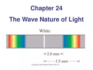
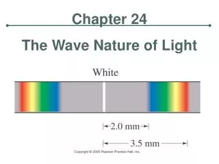
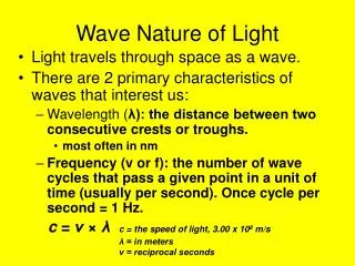
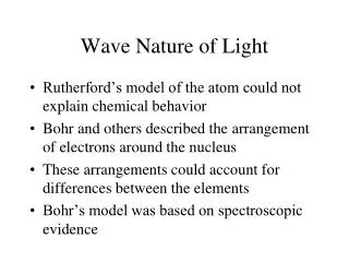
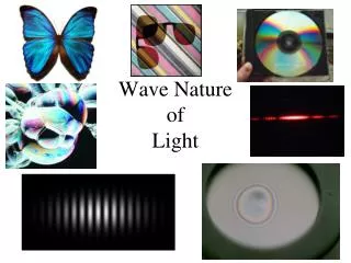
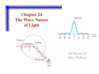
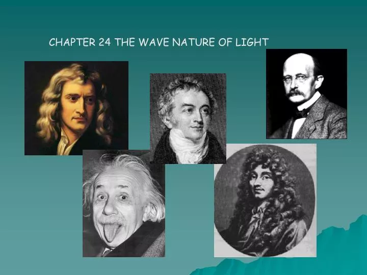
CHAPTER 24 THE WAVE NATURE OF LIGHT.

E N D
Huygen's principle, which states that all points along a wave front act as if they were point sources. Thus, when a wave comes against a barrier with a small opening, all but one of the effective point sources are blocked, and the light coming through the opening behaves as a single point source, so that the light emerges in all directions, instead of just passing straight through the slit.
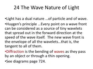
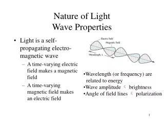
Huygens developed a means for predicting the future position of a wave front when an earlier position was know. A wave front consists of all the Points along a wave that form a crest (4) Wave fronts are perpendicular to the light rays
Diffraction occurs for waves and not for particles. A ball rolled through an opening continues in a straight line and does not bend round the barrier.
The wave model of light nicely accounts for diffraction. But the ray model cannot account for diffraction. Geometric optics using rays is successful in a wide range of situations only because normal openings and obstacles are much larger than the wavelength of the light, and so little diffraction occurs.
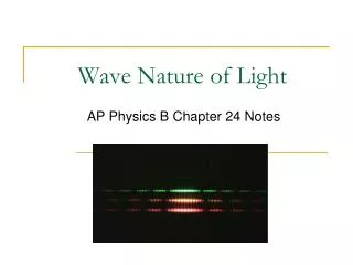
Thomas Young's Double Slit Experiment In 1801, an English physicist named Thomas Young performed an experiment that strongly inferred the wave-like nature of light.
Young thought that if light were wave-like in nature, then it should behave in a manner similar to a set of two ripple patterns in a pond. If that is true, then the light should produce areas of constructive and destructive interference just like the ripples in the pond.
If light is a particle… If light is a particle, then only the couple of rays of light that hit exactly where the slits are will be able to pass through.
If light is a wave… There are still only two light rays that actually go through the slits, but as soon as they pass through they start to diffract.
Notice that at some points the two sets of waves will meet crest to crest, at other spots crest meets trough. Where crest meets crest, there will be constructive interference and the waves will make it to the viewing screen as a bright spot. Where crest meets trough there will be destructive interference that cancel each other out… a black spot will appear on the screen. Occurs when one ray travels an extra distance of one-half wavelength and are out of phase Occurs when the path of the two rays differ by one wavelength
To determine where the bright line fall, d sinq =ml To determine where dark lines fall,d sinq = (m + ½)l
When you set up this sort of an apparatus, there is actually a way for you to calculate where the bright lines (called fringes) will appear. There is always a middle line, which is the brightest. We call it the central fringe.
In the formula we will use, there is a variable, “m”, that is a count of how many bright fringes you are away from the central fringe. The central fringe is m = 0. The fringe to either side of the central fringe has an order of m = 1 (the first order fringe) and so on… m =2, m=3, m=4… The formula: l = dx/mL
λ = wavelength of light used (m)x = distance from central fring(m)d = distance between the slits (m) m = the order of the fringeL = length from the screen with slits to the viewing screen (m)
There is also a version of the formula where you measure the angle between the central fringe and whatever fringe you are measuring. l = dsinq/m
Observe that the nodes of the pattern are oriented along lines - known as nodal lines. Similarly, the anti-nodes in the pattern are also oriented along lines - known as anti-nodal lines. The spacing between these lines is related to the distance between the sources. As the sources move closer together, the spacing between the nodal lines and the anti-nodal lines increases. That is, the nodal and anti-nodal lines spread farther apart as the sources come closer together.
Observe that the nodes of the pattern are oriented along lines - known as nodal lines. Similarly, the anti-nodes in the pattern are also oriented along lines - known as anti-nodal lines. The spacing between these lines is related to the wavelength of the light. As the wavelength increases, the spacing between the nodal lines and the anti-nodal lines increases. That is, the nodal and anti-nodal lines spread farther apart as the wavelength gets larger.
http://micro.magnet.fsu.edu/primer/java/interference/doubleslit/http://micro.magnet.fsu.edu/primer/java/interference/doubleslit/ http://theory.uwinnipeg.ca/physics/light/node7.html http://www.sparknotes.com/physics/optics/phenom/section2.rhtml http://www.physics.utoledo.edu/~lsa/_color/10_rfr.htm http://sol.sci.uop.edu/~jfalward/lightinterference/lightinterference.html http://www.headwize.com/tech/elemnts_tech.htm