Download
1 / 13
130 likes | 812 Vues
Non-Alloyed Ohmic Contact in HEMTs. Introduction Ohmic contacts for HEMTs Non-alloyed ohmic contact technology Summary. 2004. 6. 22. Microwave devices 2003-21577 노 훈 희. Introduction - ohmic contacts. To allow electrical current to flow into or out of the semiconductor

E N D
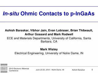
Non-Alloyed Ohmic Contact in HEMTs • Introduction • Ohmic contacts for HEMTs • Non-alloyed ohmic contact technology • Summary 2004. 6. 22. Microwave devices 2003-21577 노 훈 희
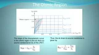
Introduction - ohmic contacts • To allow electrical current to flow into or out of the semiconductor • Linear I-V characteristic • Stable over time & temperature • Little parasitic resistance • Importance of Ohmic contact • The contact resistance in a GaAs FET may be half of the total (parasitic) source resistance • Noise figure is particularly sensitive to such resistance
Ohmic contacts • Alloyed Ohmic contact – widely used • AuGe/Ni, AuGe/Au, AuGe/Ni/Au, Au/Ge/Ni/Ag, Au/Ge/Ni • Non-alloyed Ohmic contact • Au/Pt/Ti, Pd/Ge, Pd/Sn, Pd/Sn/Au, • Regrown Ohmic contact
Non-alloyed Ohmic contact Technology The Au/Ge/Ni system has been widely used as the ohmic contact th the devices, but it has some drawbacks, - roughness - non uniformity - poor thermal stability • Advantage of non-alloyed ohmic contact • Extremely short ohmic length with low parasitic RS • Sharply defined ohmic edges can be obtained in the device channel • Direct connection between the source/drain and gate with the same metal • Provides very good surface morphology • Good gate-level lithographic definition in integrated circuits • RC shows excellent uniformity and wafer to wafer reproducibility
3.3x10⁻⁷Ω∙cm2 1.5x10⁻⁷Ω∙cm2 Mechanism of Nonalloyed Ohmic contact - 1.4E18cm3 + II ~10-6Ω∙cm2 IEEE Trans.Electron Devices, 1989
Mechanism of Nonalloyed Ohmic contact RS as a function of Loh with LSG=2um RS as a function of the spacing between the source and gate LSG IEEE Trans.Electron Devices, 1989
Inserted n+ doped InAlAs layer RC depends most significantly on two factors : - The doping level in all of the n+-doped layers - The thickness of the carrier supply layer 0.067Ωmm IEEE Trans.Electron Devices, 1996
Nonalloyed PdGe ohmic contact The gate with Ti/Pt/Au metals were not degraded at temperatures lower than 325C If the ohmic contact forming at temperatures lower than 300C is developed... Source/drain electrodes could be formed after the fabrication of the fine gate electrode It makes the self aligned gate (SAG) process possible in the fabrication of HEMT This promises more precise alignment of a fine gate between source and drain electrodes Applied physics letters, 1999
Nonalloyed PdGe ohmic contact 1.2x10⁻⁷Ω∙cm2 Applied physics letters, 1999
Nonalloyed Thermally stable Pd/Sn and Pd/Sn/Au Ohmic contacts One of the most important criteria for an ohmic contact is its thermal stability Pd/Sn Pd/Sn/Au 410C Pd/Ge IEEE Trans. Electron devices,2001
G LGS S D RS RD Intrinsic Application of Nano HEMT Issue 1 : Fine gate level Litho. - Good metal morphology → Good Mix & Match process ( optical & e-beam litho.) Issue 2 : Small RS→ Small LGS, Small RC - Self align gate process → Good gate length uniformity
Summary • A short ohmic length with low parasitic RS is a great advantage of nonalloyed ohmic contacts in high-density VLSI • The nonalloyed ohmic contact had been prescribed from actual use in a HEMT structure because of necessarily high doping concentrations, in the range of 1019cm-3 → electron turnnelling
Reference • Shigeru Kuroda, "A New Fabrication Technology for AlGaAs/GaAs HEMT LSI's Using InGaAs Nonalloyed Ohmic Contacts" IEEE TRANSACTION ON EL, 1989 • Kevin J. Chen, "High-Performance InP-Based Enhancement-Mode HEMT's Using Non-Alloyed Ohmic Contacts and Pt-Based Buried-Gate Technologies" IEEE TRANSACTION ON ED, 1996 • Kevin J. Chen, "High-Performance Enhancement-Mode InAlAs/InGaAs HEMT's Using Non-Alloyed Ohmic Contacts and Pt-Based Buried-Gate Technologies" IPRM,1995 • D.A.J.Moran, "Self-aligned 0.12um T-gate InGaAs/InAlAs HEMT technology utilising a non-annealed ohmic contact strategy" ESSDR 2003 • Jung-Woo Oh “Application of nonalloyed PdGe ohmic contact to self-aligned gate AlGaAs/InGaAs pseudomorphic high-electron-mobility transistor” Applied Physics letters, 1999 • C.K. Peng " Extremely low non-alloyed and alloyed contact resistance using an InAs cap layer on InGaAs by molecular-beam epitaxy" • S. Kuroda,"HEMT with nonalloyed ohmic contact using n+InGaAs cap layer" IEEE Electron Device Lett. 1987 • P. O'Connor, "Gold-germanium-based ohmic contacts to the two-dimensional electron gas at selectively doped semiconductor heterointerfaces" IEEE Trans. Electron. Devices 1987 • M.S.Islanm “Novel Nonalloyed Thermally Stable Pd/Sn and Pd/Sn/Au Ohmic Contacts for the Fabrication of GaAs MESFETs” IEEE trans. Electron Devices.2001