Download
1 / 22
220 likes | 349 Vues
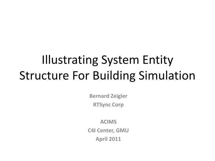
Illustrating System Entity Structure For Building Simulation. Bernard Zeigler RTSync Corp ACIMS C4I Center, GMU April 2011. Traditional Simulation Development (From Goldstein DEVS Tutorial).

E N D
Illustrating System Entity Structure For Building Simulation Bernard Zeigler RTSync Corp ACIMS C4I Center, GMU April 2011
Traditional Simulation Development (From Goldstein DEVS Tutorial) The code consists of five parts: the model parameters, which are normally supplied by the user; the initialization of a set of changing variables known as the state; a simulation loop; the state transition, which occurs repeatedly within the loop; and the simulation output, which in this case also occurs within the loop.
Traditional Simulation Development (From Goldstein DEVS Tutorial) the basic structure of the program remains. The thing to note is that the added code, shown in green, is scatteredn throughout the program.
DEVS Simulation Development (From Goldstein DEVS Tutorial) Using DEVS, simulation software is divided into a model and a simulator. Just like the traditional approach, DEVS-based simulation development is an iterative process. The difference is that, because a DEVS simulator can be reused for a variety of different models, the developer modifies only the model at each iteration. Aside from enforcing a distinction between the model and the simulator, DEVS allows complex models to be composed of simpler component models.
Coupled DEVS Model (From Goldstein DEVS Tutorial) A DEVS model generally deals with model parameters, the initial state, state transitions, and simulation output, but the simulation loop itself is part of the simulator. DEVS models are either atomic or coupled, and coupled models include various interconnected component models. Using DEVS, each enhancement requires modifications to only certain component models; this encourages collaboration.
DEVS-Based Modeling & Simulation System Entity Structure accepted by Building Simulation Community Structural Description Combine structure and component behavior Generate Model andSimulator System Models provided by the Building Simulation Community – preferable DEVS-compliant Behavior Descriptions
Introducing the System Entity Structure (SES) • The SES takes collaborative DEVS model development a major step further • The SES enables the description of families of hierarchical models such as a range of architectures for building simulations • The SES supports the development of model repositories where components developed by developers and vendors can be stored for reuse • A building architect/designer can prune the SES for a particular architecture and by transforming, evaluate it for various objectives such as energy consumption • DEVS/SOA goes an additional step to support discovery and model composition using resources of the web
SES Formal Framework The System Entity Structure (represents a design space via the elements of a system and their relationships in hierarchical and axiomatic manner Aspect : labeled decomposition relation between the parent and the children System Entity Structure A Specialization :labeled relation that expresses alternative substitutions for a component B C B1 B2 D E F Multi-aspects: aspect for which the components are all of the same kind. DS F1 F2 F3 Pruning Pruned Entity Structure 1 Pruned Entity Structure 2 Pruning: cuts off structure in a SES that is not needed to meet particular objectives Selects from a family of possible architectures A A B:B1 C B:B2 C D E F:F3 D E F:F1 D D D D D D
Basic Infrastructure Pruning Transformation PES State State State State State State State State State State State State State State State State State State State State State State State State State State State State State State State State State State State State State State State State State State State State State State State State State State State State State State External Transition External Transition External Transition External Transition External Transition External Transition External Transition External Transition External Transition External Transition External Transition External Transition External Transition External Transition External Transition External Transition External Transition External Transition Internal Transition Internal Transition Internal Transition Internal Transition Internal Transition Internal Transition Internal Transition Internal Transition Internal Transition Internal Transition Internal Transition Internal Transition Internal Transition Internal Transition Internal Transition Internal Transition Internal Transition Internal Transition State State State State State State State State State State State State State State State State State State State State State State State State State State State State State State State State State State State State State State State State State State State State State State State State State State State State State State State State State State State State State State State State State State State State State State State State time advance time advance time advance time advance time advance time advance time advance time advance time advance time advance time advance time advance time advance time advance time advance time advance time advance time advance output output output output output output output output output output output output output output output output output output Simulation Model SES Objective Experimental Frames Experimental Frame Model Car 1 Car 1 Car 1 Car 1 Car 1 Model Base Engine: Gasoline Engine Engine: Gasoline Engine Engine: Gasoline Engine Engine: Gasoline Engine Engine: Gasoline Engine Transmission:Automatic Transmission Transmission:Automatic Transmission Transmission:Automatic Transmission Transmission:Automatic Transmission Transmission:Automatic Transmission Chassis: Rear Wheel Chassis Chassis: Rear Wheel Chassis Chassis: Rear Wheel Chassis Chassis: Rear Wheel Chassis Chassis: Rear Wheel Chassis 6 Cyl Engine 6 Cyl Engine 6 Cyl Engine 6 Cyl Engine 6 Cyl Engine
NL Specification of System Entity Structure for Building and Experimental Frame From the heatFlow perspective, BuildingNEFClimate is made of Building and EFClimate ! EFClimate can be OutdoorTempSeries or OutdoorTempGenr in meansOfGeneration ! From the heatFlow perspective, EFClimate sends OutdoorTemp to Building ! From the buildingHeatFlow perspective, Building is made of BuildingEnvelope, IndoorClimate, HVACSystemNSensor,and Occupant ! From the buildingHeatFlow perspective, Building sends OutdoorTemp to BuildingEnvelope! From the buildingHeatFlow perspective, BuildingEnvelope sends OutdoorHeatTransfer to IndoorClimate! From the buildingHeatFlow perspective, HVACSystemNSensor sends HVACHeatTransfer to IndoorClimate! From the buildingHeatFlow perspective, IndoorClimate sends IndoorTemp to Occupant ! From the buildingHeatFlow perspective, IndoorClimate sends IndoorTemp to HVACSystemNSensor! From the buildingHeatFlow perspective, Occupant sends WindowChange to BuildingEnvelope! BuildingEnvelope can be WithWindow or WithoutWindow in opening ! From the control perspective, HVACSystemNSensor is made of HeatCoolSystem, Ventillator, and TempSensor ! From the control perspective,HVACSystemNSensor sends IndoorTemp to TempSensor ! From the control perspective,TempSensor sends SensorChange to HeatCoolSystem! From the control perspective,HeatCoolSystem sends HVACHeatTransfer to HVACSystemNSensor ! HeatCoolSystem can be HeaterNCooler or HeatPump in operation ! From the onOffperspective,HeaterNCooler is made of Heater and Cooler ! From the onOffperspective,HeaterNCooler sends SensorChange to Heater ! From the onOffperspective,HeaterNCooler sends SensorChange to Cooler ! From the onOff perspective, Heater sends HVACHeatTransfer to HeaterNCooler ! From the onOff perspective, Cooler sends HVACHeatTransfer to HeaterNCooler !
Top 3 Levels of Building and EF SES Coupling
SES Showing Specializations Specialization for choice of HeatNCool System Specialization for choice of outdoor weather source
Pruning Entities From Specializations selectEntityFromSpec("HeaterNCooler", “..“.."); selectEntityFromSpec("HeatPump", "operation", "HeatCoolSystem");
Pruning of SES where Separate Heater and Cooler are Selected
Transformation of SES where Separate Heater and Cooler Selected
Refinement of Experimental Frame to include Energy Consumption Transducer From the heatFlow perspective, BuildingNEFClimate is made of Building and EFEnergyConsumed ! From the heatFlow perspective, EFEnergyConsumed sends OutdoorTemp to Building ! From the heatFlow perspective, Building sends HVACHeatTransfer to EFEnergyConsumed ! From the energy perspective, EFEnergyConsumed is made of OutdoorWeather and EnergyTransd ! OutdoorWeather can be OutdoorTempSeries or OutdoorTempGenr in meansOfGeneration ! From the energy perspective, OutdoorWeather sends OutdoorTemp to EFEnergyConsumed ! From the energy perspective, EFEnergyConsumed sends HVACHeatTransfer to EnergyTransd ! //rest of SES is same as before
DEVS/SOA combines DEVS with SOA Simulation, Web Service, Geographic, Ontology Standards External Web Service-Based Models: DEVS Web Service Proxies: Model Integration Simulation Coordinator Expanding Capabilities DEVS Compliant Models DEVS/SOA is an open architecture with expanding capabilities to exploit simulation resources on the Web
The Creative Generative World of Pruning • Constraints may apply to aspects (compositions) and selections (specializations) • Constraint propagation – a selection in one place may constrain the choices in another place – can be rule based • Context dependence – selections from the same specialization can be different in different contexts (under different entities) • MultiAspects open up new contexts for pruning
Books and Web Links Rtsync.com www.acims.arizona.edu http://en.wikipedia.org/wiki/DEVS