Download
1 / 19
190 likes | 530 Vues
GBT Project Status. Paulo Moreira On behalf of the GBT team 6 November 2013 CERN, Switzerland. Outline. Radiation Hard Optical Link Architecture The GBT System GBLD Status GBTIA Status GBTX: Data Bandwidth Functionality ASIC Status Testing Status GBTX Future GBT-SCA Status

E N D
GBT Project Status Paulo Moreira On behalf of the GBT team 6 November 2013 CERN, Switzerland Paulo.Moreira@cern.ch
Outline • Radiation Hard Optical Link Architecture • The GBT System • GBLD Status • GBTIA Status • GBTX: • Data Bandwidth • Functionality • ASIC Status • Testing Status • GBTX Future • GBT-SCA Status • GBT Building Blocks Status • GBT-FPGA Status Paulo.Moreira@cern.ch
Radiation Hard Optical Link Architecture GBT GBT Versatile Link FPGA Timing & Trigger Timing & Trigger GBTX PD GBTIA DAQ DAQ LD GBLD Slow Control Slow Control Custom ASICs On-Detector Radiation Hard Electronics Off-Detector Commercial Off-The-Shelf (COTS) Paulo.Moreira@cern.ch
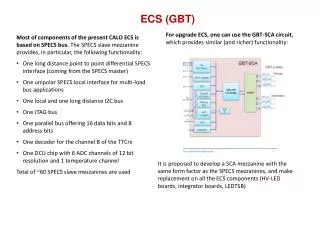
The GBT System External clock reference FEModule Clock[7:0] E – Port e-Link GBTX Phase - Shifter CLK Reference/xPLL E – Port FEModule E – Port ePLLRx GBTIA DEC/DSCR CDR E – Port data-down data-up Phase – Aligners + Ser/Des for E – Ports CLK Manager clock 80, 160 and 320 Mb/s ports GBLD SCR/ENC SER E – Port ePLLTx FEModule E – Port E – Port One 80 Mb/s port Control Logic Configuration (e-Fuses + reg-Bank) GBT – SCA JTAG I2C Slave I2C Master E – Port I2C (light) data JTAG Port I2C Port control clocks Paulo.Moreira@cern.ch
GBLD Status GBLD V4.1 • Main Specs • Bit rate 5 Gb/s (min) • Modulation: • Current sink • Single-ended/differential • Laser modulation current: 2 to 24 mA • Laser bias: 2 to 43 mA • Equalization: • Pre-emphasis/de-emphasis • Independently programmable for rising/falling edges • Supply voltage: 2.5 V • Die size: 2 mm × 2 mm • I2C programming interface • Status • Available in small quantities • Integrated in the VTRx and VTTx • Fully functional • Excellent performance • Radiation hardness proved (total dose) • Final SEU tests to be done October 2013 • Technology: 130 nm DM metal stack • Device is production ready 4.8 Gb/s, pre-emphasis on Total jitter: ≈ 25 ps Paulo.Moreira@cern.ch
LpGBLD Status Low power GBLD (LpGBLD) • Main Specs, mostly as for GBLD V4 but: • VCSEL driver only: • Lower modulation current: • 12 mA max • Power consumption reduced by 40% • VCSEL choice is determinant • Min: 138 mW • Max: 325 mW • Uses the LM stack: • It can be fabricated with GBTIA and GBTX • Status: • Devices available in small quantities • Electrically characterization done • Performance is good at ambient temperature: • Slower than GBLD V4 as expected • At high temperatures (> 70) the electrical performance degrades slightly • When convolved with the laser response at high temperatures the performance falls behind specs: • Further studies require to evaluate performance with multiple VCSEL devices Paulo.Moreira@cern.ch
GBTIA Status GBTIA V2.0 / V2.1 • Main specs: • Bit rate 5 Gb/s (min) • Sensitivity: 20 μA P-P (10-12 BER) • Total jitter: < 40 ps P-P • Input overload: 1.6 mA (max) • Dark current: 0 to 1 mA • Supply voltage: 2.5 V • Power consumption: 250 mW • Die size: 0.75 mm × 1.25 mm • Status: • Fully functional • Integrated in the VTRx • Excellent performance • Radiation hardness proved • Tested up to 200 Mrad (SiO2) • Device is production ready • LM metal stack Paulo.Moreira@cern.ch
GBTX Data Bandwidth • The GBTX supports three frame types: • “GBT” Frame • “Wide Bus” Frame • “8B/10B” Frame • “GBT” Mode • User bandwidth: 3.28 Gb/s • Up/down-links • “Wide Bus” and “8B/10B”frames are only supported for the uplink • The downlink always uses the “GBT” frame. • “8B/10B” Mode • Downlink data 8B/10B encoded • No FEC • User bandwidth: 3.52 Gb/s • “Wide Bus” Mode: • Uplink data scrambled • No FEC • User bandwidth: 4.48 Gb/s GBTX Phase - Shifter CLK Reference/xPLL E – Port ePLLRx DEC/DSCR CDR E – Port Phase – Aligners + Ser/Des for E – Ports CLK Manager SCR/ENC SER E – Port ePLLTx E – Port Control Logic Configuration (e-Fuses + reg-Bank) JTAG I2C Slave I2C Master Paulo.Moreira@cern.ch
GBTX Functionality (1/4) e-Links • 40 bi-directional e-Links • Up to 40 @ 80 Mb/s • Up to 20 @ 160 Mb/s • Up to 10 @ 320 Mb/s • e-Port data rate can be set independently for: • each group • Input / output ports • 1 bi-directional e-Link: • 80 Mb/s • 40 e-Link clocks (fixed phase) programable in frequency: • 40/80/160/320 MHz (per group) • (independently of the bit rate) • Automatic, semi-automatic or user controlled phase alignment of the incoming serial data embedded in the e-Ports • Automatic alignment • Tracks temperature and voltage variations • Transparent to the user • Works on any type of data: • DC balanced / un-balanced • A few “occasional” transition enough to ensure correct operation GBTX Phase - Shifter CLK Reference/xPLL E – Port ePLLRx DEC/DSCR CDR E – Port Phase – Aligners + Ser/Des for E – Ports CLK Manager SCR/ENC SER E – Port ePLLTx E – Port Control Logic Configuration (e-Fuses + reg-Bank) JTAG I2C Slave I2C Master Paulo.Moreira@cern.ch
GBTX Functionality (2/4) e-Links Special cases • 8B/10B mode: • 44 input (max @ 80 Mb/s) • 36 output (max @ 80 Mb/s) • (Four outputs reused as inputs) • Wide-Bus mode: • 56 input (max @ 80 Mb/s) • 24 output (max @ 80 Mb/s) • (16 “outputs” reused as inputs) e-Links electrical characteristics • Drivers: • SLVS signaling • Receivers: • SLVS/LVDS signaling GBTX Phase - Shifter CLK Reference/xPLL E – Port ePLLRx DEC/DSCR CDR E – Port Phase – Aligners + Ser/Des for E – Ports CLK Manager SCR/ENC SER E – Port ePLLTx E – Port Control Logic Configuration (e-Fuses + reg-Bank) JTAG I2C Slave I2C Master Paulo.Moreira@cern.ch
GBTX Functionality (3/4) Phase-Shifter • 8 independent clocks • Programable in frequency: • 40 / 80 / 160 / 320 MHz • Programable in phase: • 0 to 360◦ • Phase resolution: 50 ps • (for all frequencies) • Clock driver electrical levels: • SLVS Reference clock: • On package crystal • Built-in crystal oscillator • Built-in VCXO based PLL (xPLL) • External reference can used as well GBTX Phase - Shifter CLK Reference/xPLL E – Port ePLLRx DEC/DSCR CDR E – Port Phase – Aligners + Ser/Des for E – Ports CLK Manager SCR/ENC SER E – Port ePLLTx E – Port Control Logic Configuration (e-Fuses + reg-Bank) JTAG I2C Slave I2C Master Paulo.Moreira@cern.ch
GBTX Functionality (4/4) Chip Control • e-Fuse register bank for burn in configuration • Standalone operation • Ready at power up • Dynamic configuration and control • I2C Slave interface • IC control channel trough the optical link • Watchdog circuit for chip operation supervision. GBLD Control • GBLD dedicated I2C master interface • Copies configuration burned in the GBTX into the GBLD at start-up • Allows to program the GBLD either through the IC channel or through the I2C slave port GBTX Phase - Shifter CLK Reference/xPLL E – Port ePLLRx DEC/DSCR CDR E – Port Phase – Aligners + Ser/Des for E – Ports CLK Manager SCR/ENC SER E – Port ePLLTx E – Port Control Logic Configuration (e-Fuses + reg-Bank) JTAG I2C Slave I2C Master Paulo.Moreira@cern.ch
GBTX Status • GBTX submitted for fabrication on the 6th of August 2012 • Prototypes: • 120 ASICs (bare die) available since December 2012 • First packaged chips available May 2013 • Long design/production cycle! • Due to a manufacturing error the package presented a short-circuit between the power and ground planes • This caused the loss of 60 die and testing delays • “Preliminary testing” could nonetheless be done by drilling the short-circuit in a few packages at the loss of a few connections! • Fully functional packaged chips were finally delivered September 2013 Total height including solder balls: ~3 mm 17 mm Paulo.Moreira@cern.ch 17 mm
GBTX Testing Status Paulo.Moreira@cern.ch
GBTX Future • Q4 – 2013 • First SEU test done the 31st October: • Data is now being analysed to determine the SEU cross sections at the tested LETs • Total dose irradiation tests: December • Chip characterization: October – December • Samples available for prototyping: December • Only small quantities available (< 60) • (Remember that we have lost a substantial fraction due to the packaging problem) • GBT – SCA submission: 18th November • Q1 – 2014 • Depending on the SEU test results small changes might be required to improve the robustness of the circuit • Although the circuit is fully functional a “a few small corners need to be rounded” to make it “plug-and-play” for the users • Q2 – 2014 • Split Engineering Run to produce in quantities: • GBTX • GBTIA • GBLD V4/V5 • GBT-SCA (if fully tested before February) • Q3 – 2014 • Chips available from the foundry • ASIC Packaging • Q4 – 2014 • ASIC production testing • First production ASICs distributed to the users Paulo.Moreira@cern.ch
GBT-SCA Status • Analog Circuitry • ADC block • Design development outsourced to an IP vendor. • Design is based on the DCU ADC architecture. • Integration work of the IP block is on going. • DAC • Building block borrowed from the MEDIPIX-3 project. • Digital Circuitry • RTL code extensively redesigned during last year. • Development of a test bench based on System Verilog • Development of a hardware test benched based on an FPGA development board. • ePort (with HDLC transmission protocol) • Chip Assembly and prototype submission • Final Place & Route work is on going. • Target tape out date: • MOSIS MPW run in November 2013 Paulo.Moreira@cern.ch
GBT Building Blocks (IP) Status Available “IP” to facilitate the implementation ofe-Link transceivers in the frontend ASICs: • SLVS Receiver • Wire-bond, DM metal stack • C4, LM metal stack • SLVS Driver • Wire-bond, DM metal stack • C4, LM metal stack • SLVS Bi-directional • C4, LM metal stack • HDLC transceiver • Synthesizable Verilog • 7B/8B CODEC • Synthesizable Verilog • ePLL-FM • Frequency MultiplierPLL • Radiation Hard • 130 nm CMOS technology with the DM metal stack (3-2-3). • Input frequencies: 40/80/160 MHz • Output frequencies: 160/320 MHz regardless the input frequency • Programmable phase of the output clocks with a resolution of 11.25° for the 160 MHz clock and 22.5° for the 320 MHz clock • Programmable charge pump current, loop filter resistance and capacitance to optimize the loop dynamics • Supply voltage: 1.2 V - 1.5 V • Nominal power consumption: 20 mW @ 1.2 V - 30 mW @1.5 V • Operating temperature range: -30°C to 100°C • ePLL-CDR (currently under testing) • Data rate: 40/80/160/320 Mbit/s • Output clocks: data clock + 40/80/160/320 MHz with programmable phase • Internal or external calibration of the VCO frequency • Possibility to use it as a frequency multiplier PLL without applying input data • Programmable charge pump current, loop filter resistance and capacitance to optimize the loop dynamics • Supply voltage: 1.2 V - 1.5 V • Operating temperature range: -30°C to 100°C • Prototype fabrication: May 2013 ePLL- FM Paulo.Moreira@cern.ch
GBT – FPGA Status • Aim: • Implement the GBT serial link in all its flavours as an IP core for most of the current FPGAs used on Back-End boards for upgrades • Propose an emulation of the E-links for Front-End chip emulation on FPGA • On-going firmware updates • Serial link encoding schemes • Reed-Solomon (used in GBT frame operation mode), • 8b/10b (using hardIP if possible to reduce resources) • Wide-bus • Fixed latency version • E-links modes • GBT modes x2, x4 and x8 • Wide bus mode • 8b/10b mode • IC channel protocol (not yet started) • Available or targeted FPGA • Altera: • Stratix II and IV (tested with the GBT-SerDes ASIC) • Cyclone V GT (tested with the real GBTx ASIC) • Stratix V (to be done) • Xilinx: • Virtex 5 and 6 (tested with the GBT-SerDes ASIC) • Kintex 7 (on-going) • Virtex 7 (on-going) • Available or targeted Reference designs • Xilinx: • Virtex 5: ML523 • Virtex 6: ML605 and GLIB • Kintex 7: KC705 • Virtex 7: VC705 • Altera: • Stratix II Gx:PCIe evaluation kit • Stratix IV: PCIe evaluation kit • Cyclone V GT: evaluation kit and GBTx Stand Alone Tester (SAT board) • Project Resources • 50% of one Fellow since this summer • More than 70 users registered • A sharepoint site: https://espace.cern.ch/GBT-Project/GBT-FPGA/default.aspx • A SVN repository: • https://svnweb.cern.ch/cern/wsvn/ph-ese/be/gbt_fpga • Contact us: • Sophie.baron@cern.ch • Manoel.Barros.Marin@cern.ch GLIB board (Virtex 6) KC705 (Kintex 7) Paulo.Moreira@cern.ch
2014 – and beyond, LpGBTX: Activities / Manpower / Budget The LpGBT project: Serious development effort to start Q2 2014 • LpGBTIA • Technology: 65 nm CMOS • Manpower: 1.5 MY (design and testing) • LpGBLD10 • Technology: 130 nm CMOS • Manpower: 2 MY (design , packaging and testing) • LpGBTX • Technology: 65 nm CMOS • Two packaging flavours: • “Tracker” & “General Purpose” • Manpower: • Design: 8 MY • Packaging: 1 MY • Testing: 2 MY • We have to seriously consider “building” a stable LpGBT team if a LpGBT chipset is to be a reality in useful time! • The move to 65 nm and Low Power is not just a “copy-paste exercise”!!! • The LpGBT has not yet been defined as an approved “project” or “common project”: • No budget and manpower assigned to it yet! Paulo.Moreira@cern.ch