Download
1 / 163
1.7k likes | 2.12k Vues
Chapter 4: network layer. chapter goals: understand principles behind network layer services: network layer service models forwarding versus routing how a router works routing (path selection) broadcast, multicast instantiation, implementation in the Internet. 4.1 introduction

E N D
Chapter 4: network layer chapter goals: • understand principles behind network layer services: • network layer service models • forwarding versus routing • how a router works • routing (path selection) • broadcast, multicast • instantiation, implementation in the Internet Network Layer
4.1 introduction 4.2 virtual circuit and datagram networks 4.4 IP: Internet Protocol datagram format IPv4 addressing ICMP (Internet Control Message Protocol ) IPv6 4.5 routing algorithms link state distance vector hierarchical routing 4.6 Internet routing protocols RIP OSPF BGP 4.7 broadcast and multicast routing Chapter 4: outline Network Layer
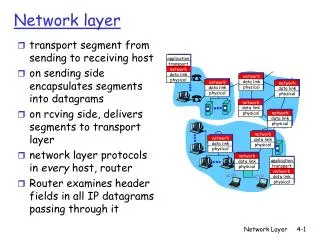
transport segment from sending to receiving host on sending side encapsulates segments into datagrams on receiving side, delivers segments to transport layer network layer protocols in everyhost, router router examines header fields in all IP datagrams passing through it network data link physical network data link physical network data link physical network data link physical network data link physical network data link physical network data link physical network data link physical network data link physical network data link physical network data link physical application transport network data link physical application transport network data link physical Network layer Network Layer
Two key network-layer functions analogy: drive from SB to Mannheim • routing: process of planning trip from source to dest. • forwarding: process of getting through single interchange • forwarding: move packets from router’s input to appropriate router output (within router!) • routing: determine route taken by packets from source to dest. (on network level) • routing algorithms Network Layer
routing algorithm local forwarding table header value output link routing algorithm determines end-end-path through network forwarding table determines local forwarding at this router 0100 0101 0111 1001 3 2 2 1 value in arriving packet’s header 1 0111 2 3 Interplay between routing and forwarding Network Layer
Connection setup • after routing and forwarding the 3rdimportant function in somenetwork architectures: • e.g. ATM • before datagrams flow, two end hosts and intervening routers establish virtual connection • routers along chosen path handshake with each other • network vs transport layer connection service: • transport: between two processes running in certain hosts • network: between two hosts (may also involve intervening routers in case of VCs) Network Layer
example services for individual datagrams: guaranteed delivery guaranteed delivery with less than 40 msec delay example services for a flow of datagrams: in-order datagram delivery guaranteed minimum bandwidth (emulate single link with specified bit rate) Network service model Service models for transporting datagrams from sender to receiver? Network Layer
Network layer service models: Guarantees ? Network Architecture Internet ATM ATM ATM ATM Service Model best effort CBR (constant) VBR (variable) ABR (available) UBR (unspecified) Congestion feedback no (inferred via loss) no congestion no congestion yes no Bandwidth none constant rate guaranteed rate guaranteed minimum none Loss no yes yes no no Order no yes yes yes yes Timing no yes yes no no Network Layer
4.1 introduction 4.2 virtual circuit and datagram networks 4.4 IP: Internet Protocol datagram format IPv4 addressing ICMP IPv6 4.5 routing algorithms link state distance vector hierarchical routing 4.6 routing in the Internet RIP OSPF BGP 4.7 broadcast and multicast routing Chapter 4: outline Network Layer
Connection, connection-less service • network with network-layer connectionlessservice is called datagram network (e.g. the Internet!) • network with network-layer connection service is called virtual-circuit network • analogous to TCP/UDP connection-oriented / connectionless transport-layer services, but: • service:host-to-host • no choice:network provides one or the other • implementation:in network core Network Layer
VC setup before data can flow (determine path, reserve resources, add forwarding table entries in routers) after transmission is over: VC teardown every router on source-dest path maintains “state” for each passing connection (entry in forwarding table) link, router resources (bandwidth, buffers) may be allocated to VC (dedicated resources = predictable service) Virtual circuits Network Layer
VC implementation a VC consists of: • path from source to destination • VC numbers, one number for each link along path • entries in forwarding tables in routers along path • packet belonging to VC carries a VC number (rather than dest address) • VC number can be changed on each link => routers replace old VC numbers of traversing packets by new ones (obtained from forwarding table) • Why do numbers change? (1) reduces length of VC number field, (2) links do not have to synchronize number during setup (choose independently) Network Layer
VC forwarding table 22 32 12 3 1 2 VC number interface number forwarding table in northwest router: Incoming interface Incoming VC # Outgoing interface Outgoing VC # 1 12 3 22 2 63 1 18 3 7 2 17 1 97 3 87 … … … … Example: initial VC number is 12, then changed to 22, then to 32. Network Layer
signaling protocols are used for setup and teardown of VCs (make routers aware of VC => add/remove entries in forwarding tables) setup messages are propagated on special virtual circuit not used in today’s Internet application transport network data link physical application transport network data link physical Virtual circuits: signaling protocols 6. receive data 5. data flow begins 4. call connected 3. accept call 1. initiate call 2. incoming call Network Layer
Internet (datagram) data exchange among computers “elastic” service, no strict timing req. many link types (Ethernet, radio, satellite, fiber,...) different characteristics uniform service difficult “smart” end systems (computers) simple inside network, complexity at “edge” ATM (VC) evolved from telephony human conversation: strict timing, reliability requirements need for guaranteed service simple end systems (rotary) telephones complexity inside network Datagram vs VC network Network Layer
no connection setup at network layer routers: no state about end-to-end connections no network-level concept of “connection” packets forwarded using destination host address application transport network data link physical application transport network data link physical Datagram networks 1. send datagrams 2. receive datagrams Network Layer
> 4 billion IP addresses (32 bit), so rather than list individual destination address list range of addresses (aggregate table entries) 1 3 2 Datagram forwarding table routing algorithm local forwarding table dest address output link address-range 1 address-range 2 address-range 3 address-range 4 3 2 2 1 IP destination address in arriving packet’s header Network Layer
Datagram forwarding table Destination Address Range 11001000 00010111 00010000 00000000 through 11001000 00010111 00010111 11111111 11001000 00010111 00011000 00000000 through 11001000 00010111 00011000 11111111 11001000 00010111 00011001 00000000 through 11001000 00010111 00011111 11111111 otherwise Link Interface 0 1 2 3 Note that for instance the first interval covers all addresses with prefix 11001000 00010111 00010 Network Layer
Datagram forwarding table Prefix Match 11001000 00010111 00010 11001000 00010111 00011000 11001000 00010111 00011 otherwise Link Interface 0 1 2 3 which interface? DA: 11001000 00010111 00010110 10100001 What if an address has a match with several entries? Network Layer
Prefix matching longest prefix matching when looking for forwarding table entry for given destination address, use longest address prefix that matches destination address. Link interface 0 1 2 3 Destination Address Range 11001000 00010111 00010*** ********* 11001000 00010111 00011000 ********* 11001000 00010111 00011*** ********* otherwise examples: which interface? DA: 11001000 00010111 00011000 10101010 Network Layer
4.1 introduction 4.2 virtual circuit and datagram networks 4.4 IP: Internet Protocol datagram format IPv4 addressing ICMP IPv6 4.5 routing algorithms link state distance vector hierarchical routing 4.6 routing in the Internet RIP OSPF BGP 4.7 broadcast and multicast routing Chapter 4: outline Network Layer
network layer functions of hosts and routers: • IP protocol • addressing conventions • datagram format • packet handling conventions forwarding table The Internet: a datagram network transport layer: TCP, UDP • routing protocols • path selection • RIP, OSPF, BGP network layer • ICMP protocol • error reporting • router “signaling” link layer physical layer Network Layer
IP protocol version number 32 bits total datagram length (bytes) header length (bytes) type of service head. len ver length for fragmentation/ reassembly (discussed later) fragment offset e.g. priority => requires low delay flgs 16-bit identifier upper layer time to live header checksum max number of remaining hops (decr. at each router) 32 bit source IP address 32 bit destination IP address upper layer protocol to deliver payload to (e.g. id 6 => TCP) options (if any) data (variable length, typically a TCP or UDP segment) IP datagram format how much overhead? • 20 bytes of TCP • 20 bytes of IP • = 40 bytes Network Layer
network links have MTU (max.transfer size) - largest possible link-level frame different link types, different MTUs e.g. Ethernet 1500 bytes, some wide-area links 576 bytes large IP datagram divided (“fragmented”) within net one datagram becomes several datagrams “reassembled” only at final destination (before given to transport layer) IP header bits used to identify, order related fragments … … reassembly IP fragmentation, reassembly fragmentation: in: one large datagram out: 3 smaller datagrams Network Layer
length =1040 length =4000 length =1500 length =1500 ID =77 ID =77 ID =77 ID =77 fragflag =0 fragflag =1 fragflag =1 fragflag =0 offset =370 offset =185 offset =0 offset =0 one large datagram becomes several smaller datagrams IP fragmentation, reassembly example: • 4000 byte datagram • (20 byte header + 3980 byte of IP payload) • MTU = 1500 bytes 1480 bytes in data field offset = 1480/8 offset counts blocks of 8 Bytes • last fragment has flag bit 0 • 1480+1480+1020= 3980 Network Layer
4.1 introduction 4.2 virtual circuit and datagram networks 4.4 IP: Internet Protocol datagram format IPv4 addressing ICMP IPv6 4.5 routing algorithms link state distance vector hierarchical routing 4.6 routing in the Internet RIP OSPF BGP 4.7 broadcast and multicast routing Chapter 4: outline Network Layer
IP address: 32-bit identifier for interface in host or router interface: connection between host/router and physical link routers typically have multiple interfaces host typically has one active interface (e.g., wired Ethernet, wireless 802.11) one IP address associated with each interface 223.1.1.2 223.1.3.27 IP addressing: introduction 223.1.1.1 223.1.2.1 223.1.1.4 223.1.2.9 223.1.1.3 223.1.2.2 223.1.3.2 223.1.3.1 dotted decimal notation: 223.1.1.1 = 11011111 00000001 00000001 00000001 223 1 1 1 Network Layer
Q: how are interfaces actually connected? 223.1.1.2 223.1.3.27 IP addressing: introduction 223.1.1.1 223.1.2.1 223.1.1.4 223.1.2.9 223.1.1.3 223.1.2.2 A: wired Ethernet interfaces connected by Ethernet switches 223.1.3.2 223.1.3.1 For now: don’t need to worry about how one interface is connected to another (with no intervening router) => next chapter A: wireless WiFi interfaces connected by WiFi base station Network Layer
IP address: subnet part - high order bits host part - low order bits what’s a subnet ? device interfaces with same subnet part of IP address can physically reach each other without intervening router subnet Subnets 223.1.1.1 223.1.2.1 223.1.1.2 223.1.1.4 223.1.2.9 223.1.2.2 223.1.3.27 223.1.1.3 223.1.3.2 223.1.3.1 network consisting of 3 subnets Network Layer
recipe to determine the subnets, detach each interface from its host or router, creating islands of isolated networks each isolated network is called a subnet 223.1.1.0/24 223.1.2.0/24 223.1.1.1 223.1.2.1 223.1.1.2 223.1.1.4 223.1.2.9 223.1.2.2 223.1.3.27 223.1.1.3 223.1.3.2 223.1.3.1 223.1.3.0/24 subnet Subnets subnet mask: /24 Network Layer
how many? Subnets 223.1.1.2 223.1.1.1 223.1.1.4 223.1.1.3 223.1.7.0 223.1.9.2 223.1.9.1 223.1.7.1 223.1.8.1 223.1.8.0 223.1.2.6 223.1.3.27 223.1.2.1 223.1.2.2 223.1.3.1 223.1.3.2 Network Layer
IP addressing: CIDR CIDR:Classless InterDomainRouting • approach for efficient use of 32-bit addresses (reduce size of routing tables, see later how) • subnet portion of address of arbitrary length (must not be 24 bits) • address format: a.b.c.d/x, where x is # bits in subnet portion of address host part subnet part/prefix 11001000 00010111 00010000 00000000 200.23.16.0/23 How many addresses can the subnet have at most? Network Layer
IP addresses: how to get one? Q: how does a network (belonging e.g. to some university) get subnet part of IP addr? A: gets allocated portion of its provider ISP’s address space ISP's block 11001000 00010111 00010000 00000000 200.23.16.0/20 Organization 0 11001000 00010111 00010000 00000000 200.23.16.0/23 Organization 1 11001000 00010111 00010010 00000000 200.23.18.0/23 Organization 2 11001000 00010111 00010100 00000000 200.23.20.0/23 ... ….. …. …. Organization 7 11001000 00010111 00011110 00000000 200.23.30.0/23 Network Layer
200.23.16.0/23 200.23.18.0/23 200.23.30.0/23 200.23.20.0/23 . . . . . . Hierarchical addressing: route aggregation hierarchical addressing allows efficient advertisement of routing information: Organization 0 Organization 1 “Send me anything with addresses beginning 200.23.16.0/20” Organization 2 Fly-By-Night-ISP Internet Organization 7 “Send me anything with addresses beginning 199.31.0.0/16” ISPs-R-Us Routers use longest prefix matching to determine destination (more details later)! Network Layer
IP addressing: how to get a block? Q: how does an ISP get block of addresses? A:ICANN: Internet Corporation for Assigned Names and Numbers http://www.icann.org/ • allocates addresses • manages DNS root servers • assigns domain names, resolves domain name disputes Network Layer
IP addresses: how to get one? Q: How does a host get IP address? • hard-coded by system admin in a file • Windows: control-panel->network->configuration->tcp/ip->properties • UNIX: /etc/rc.config • DHCP:Dynamic Host Configuration Protocol: dynamically get IP address • typically for desktop computers and laptops • “plug-and-play” Network Layer
DHCP: Dynamic Host Configuration Protocol • allows host to dynamically obtain its IP address from network server when it joins network • also allows to renew lease on address in use • allows to reuse of addresses (only hold address while connected/“on”) since not all customers of an ISP are online at the same time • support for mobile users who want to join network (more shortly) => switch subnet while moving with laptop DHCP overview: • host broadcasts “DHCP discover” msg to find DHCP server • DHCP server(s) responds with “DHCP offer” msg • host requests IP address: “DHCP request” msg • DHCP server sends address: “DHCP ack” msg note that several DHCP server may send offers Network Layer
DHCP client-server scenario DHCP server 223.1.1.0/24 223.1.2.1 223.1.1.1 223.1.1.2 arriving DHCP client needs address in this network 223.1.1.4 223.1.2.9 223.1.2.2 223.1.3.27 223.1.1.3 223.1.2.0/24 if no DHCP server is present in a subnet, the router can act as a DHCP relay agent (forwards request to DHCP server) 223.1.3.2 223.1.3.1 223.1.3.0/24 Network Layer
DHCP discover src : 0.0.0.0, 68 dest.: 255.255.255.255,67 yiaddr: 0.0.0.0 transaction ID: 654 DHCP client-server scenario DHCP server: 223.1.2.5 arriving client 1st UDP packet: source port: 68 destination port: 67 DHCP offer src: 223.1.2.5, 67 dest: 255.255.255.255, 68 yiaddrr: 223.1.2.4 transaction ID: 654 lease time: 3600 secs DHCP request src: 0.0.0.0, 68 dest:: 255.255.255.255, 67 yiaddrr: 223.1.2.4 transaction ID: 654 lease time: 3600 secs • still broadcast here • other servers know • that client decided for • different offer DHCP ACK src: 223.1.2.5, 67 dest: 255.255.255.255, 68 yiaddrr: 223.1.2.4 transaction ID: 654 lease time: 3600 secs Network Layer
DHCP: more than IP addresses DHCP returns: • IP address • address of first-hop router for client • name and IP address of DNS sever • network mask (indicating network versus host portion of address) Network Layer
DHCP UDP IP Eth Phy DHCP UDP IP Eth Phy DHCP DHCP DHCP DHCP DHCP DHCP DHCP DHCP DHCP DHCP DHCP: example • connecting laptop needs its IP address, addr of first-hop router, addr of DNS server: use DHCP • DHCP request encapsulated in UDP, encapsulated in IP, encapsulated in 802.3 Ethernet 168.1.1.1 • broadcast on LAN, received at router running DHCP server router with DHCP server built into router Network Layer
DHCP UDP IP Eth Phy DHCP UDP IP Eth Phy DHCP DHCP DHCP DHCP DHCP DHCP DHCP DHCP DHCP DHCP: example • DHCP server sends DHCP ACK containing client’s IP address, IP address of first-hop router for client, name & IP address of DNS server • client now knows its IP address, name and IP address of DNS server, IP address of its first-hop router router with DHCP server built into router Network Layer
NAT: network address translation Goal: connect subnet (with probably growing number of hosts) to Internet without having to allocate growing address ranges rest of Internet local network (e.g., home network) 10.0.0/24 10.0.0.1 10.0.0.4 10.0.0.2 138.76.29.7 10.0.0.3 alldatagrams leaving local network have same single source NAT IP address: 138.76.29.7,different source port numbers datagrams with source or destination in this network have 10.0.0/24 address for source, destination (as usual) Network Layer
NAT: network address translation motivation: local network uses just one IP address as far as outside world is concerned: • range of addresses not needed from ISP: just one IP address for all devices • can change addresses of devices in local network without notifying outside world • devices inside local net not explicitly addressable, visible by outside world (a security plus) Network Layer
NAT: network address translation Private IPv4 address spaces (RFC 1918) : IP address range CIDR block 10.0.0.0 - 10.255.255.255 10.0.0.0/8 172.16.0.0 - 172.31.255.255 172.16.0.0/12 192.168.0.0 - 192.168.255.255 192.168.0.0/16 Network Layer
NAT: network address translation implementation: NAT router must: • outgoing datagrams:replace (source IP address, port #) of every outgoing datagram to (NAT IP address, new port #) . . . remote clients/servers will respond using (NAT IP address, new port #) as destination addr • remember (in NAT translation table)every (source IP address, port #) to (NAT IP address, new port #) translation pair • incoming datagrams:replace (NAT IP address, new port #) in dest fields of every incoming datagram with corresponding (source IP address, port #) stored in NAT table Network Layer
3 1 2 4 S: 10.0.0.1, 3345 D: 128.119.40.186, 80 S: 138.76.29.7, 5001 D: 128.119.40.186, 80 1:host 10.0.0.1 sends datagram to 128.119.40.186, 80 2:NAT router changes datagram source addr from 10.0.0.1, 3345 to 138.76.29.7, 5001, updates table S: 128.119.40.186, 80 D: 10.0.0.1, 3345 S: 128.119.40.186, 80 D: 138.76.29.7, 5001 NAT: network address translation NAT translation table WAN side addr LAN side addr 138.76.29.7, 5001 10.0.0.1, 3345 …… …… 10.0.0.1 10.0.0.4 10.0.0.2 138.76.29.7 10.0.0.3 4:NAT router changes datagram dest addr from 138.76.29.7, 5001 to 10.0.0.1, 3345 3:reply arrives dest. address: 138.76.29.7, 5001 Network Layer
NAT: network address translation • 16-bit port-number field: • 60,000 simultaneous connections with a single LAN-side address! • NAT is controversial: • port number should not be used for addressing hosts but for addressing processes • violates end-to-end argument (hosts should talk directly with each other) • NAT possibility must be taken into account by app designers, e.g., P2P applications • address shortage should instead be solved by IPv6 http://www.computerweekly.com/feature/Do-we-really-need-to-have-IPv6-when-Nat-conserves-address-space-and-aids-security Network Layer
NAT traversal problem • client wants to connect to server with address 10.0.0.1 • server address 10.0.0.1 local to LAN (client can’t use it as destination addr) • only one externally visible NATed address: 138.76.29.7 • TCP through many-to-one NAT is always "outward only" by default • solution1: statically configure NAT to forward incoming connection requests at given port to server • e.g., (123.76.29.7, port 25000) always forwarded to 10.0.0.1 port 25000 10.0.0.1 client ? 10.0.0.4 138.76.29.7 NAT router Network Layer
10.0.0.1 NAT router NAT traversal problem • solution 2: use the Universal Plug and Play (UPnP) Protocol. Allows local host to request NAT mapping between its • (private IP address, private port number) and the (public IP address, public port number) • if NAT accepts, nodes from outside can connect via TCP to the (public IP address, public port number) Around 40-50 million network-enabled devices are at risk due to vulnerabilities found in the Universal Plug and Play (UPnP) protocol (detected in Jan 2013) “Security Flaws in Universal Plug and Play: Unplug, Don't Play.” https://community.rapid7.com/docs/DOC-2150 Network Layer