Download
1 / 28
280 likes | 439 Vues
Axial Booms. Jeremy McCauley Aerospace Engineer Space Sciences Laboratory, UCB jeremymc@ssl.berkeley.edu. Axial Booms (AXB) . Jeremy McCauley Aerospace Engineer Space Sciences Laboratory, UCB jeremymc@ssl.berkeley.edu. Spacecraft +Z. AXB. AXB. EFW AXB Overall Flow. Design. PDR.

E N D
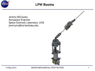
Axial Booms Jeremy McCauley Aerospace Engineer Space Sciences Laboratory, UCB jeremymc@ssl.berkeley.edu
Axial Booms (AXB) Jeremy McCauley Aerospace Engineer Space Sciences Laboratory, UCB jeremymc@ssl.berkeley.edu Spacecraft +Z AXB AXB
EFW AXBOverall Flow Design PDR ETU Build ETU Test Peer Review July 28 Flight DWG Release • PDR • RFAs: 6 AXB related, 6 Closed • Peer Review • AIs: 4 AXB related, 4 implemented • Suggestions: 11 AXB related, 11 implemented • CDR • RFAs: 1 AXB related, 1 closed CDR Sept 30- Oct 1 Flight Build Functional Deploy PER Flight Test
EFW AXBOverview Design Drivers Basic Design Description Changes Since CDR Integration and Testing (I&T)
EFW AXBDesign Drivers Deploy spherical electric fields probes up to 7 meters from center of spacecraft with an E-Field sensor and preamp at the end. Length adjustable (longer only) on orbit with a resolution of +/- 0.5 cm Interface to spacecraft to support deployable booms. Meet straightness requirement (< 1° from spin axis). Provide relief for CTE mismatch between Gr/E Tube and SC body. Provide a connector for test input to the sensor accessible during all integration phases. Total Mass not to exceed 8.57 kg (Each AXB Unit to not exceed 3.64 kg; AXB Tube to not exceed 1.29 kg) Interface Operational Temperature Range: -25 to +55C (TBR) Interface Survival Temperature Range: -30 to +60C (TBR)
EFW AXBConcept Axial Boom Unit (AXB) Sensors Extended from SC on Stacers Compact for Launch Rigid after Deploy Adjustable Length Upper Boom Unit (+Z) Lower Boom Unit (-Z)
EFW AXBOrder of Deploy • Stowed Unit • Unpowered • Fully Restrained • Step 1: Whip Deploy • Frangibolt Actuated • Spring Powered +Z SC Axis • Step 2: Stacer Deploy • Frangibolt Release • Motor Driven (3 cm/s) • Length Adjustable • Fault Analysis in Backup Slides
EFW AXBGlue Bond Margins * Joint Strength is derated according to surface preparation requirements as discussed in HTN-102050-017, dated 06/15/2000, as received from Chris Smith, UCB/SSL.
EFW AXBThermal Thermally Coupled to the SC Spherical Electric Fields Probe, Whip and Hinge: Coated with DAG 213 Stacer: Mill Finish Elgiloy Moving DAD: Alodine (1500, Clear, 300s immersion) Electroless Nickel Plating with Teflon Impregnate Stationary Deploy Assy: Alodine (1500, Clear, 300s immersion) Electroless Nickel Plating with Teflon Impregnate End Supported Tube M55 Graphite Epoxy Aluminum End Fittings Alodine (1500, Clear, 300s immersion)
EFW AXBOrder of Assembly Assemble Caging Mech Preamp Mech Assembly Test Preamp PWB Whip and Cage Mechanical Functional Integrate Whip and Cage Assemble Sphere, Whip and Preamp Assemble Whip Paint: Whip, Stacer and Sphere Whip and Cage Electrical Functional Assemble Stacer Assemble Stacer Assembly Assemble Doors Assemble DAD Assemble Stacer Mechanism Motor Burn In Harness Motor Harness Assembly Harness SW1 Assemble Direct Drive (-500) StacerMech Functional,Length & Runout Measurement, Continuity Check Harness Diode Block PER
EFW AXBChanges Since CDR - RFAs RFA #12 DESCRIPTION: Verify the sphere caging release mechanism has no gapping that may increase the Frangibolt required strain for proper release. RESOLUTION: The process of assembly was incorporated into the Caging Mechanism Assembly Procedure. Subassemblies are assembled separately and then integrated loose to allow the various parts to remove gapping. The Frangibolt interface is clamped and the bolts tightened.
EFW AXBChanges Since CDR - PFRs RBSP-EFW-PFR-002 AXB EMI Shield Cure Sample - CLOSED RBSP-EFW-PFR-003 AXB Tube Shipment - CLOSED RBSP-EFW-PFR-005 Auditor AXB Tube Bump - CLOSED RBSP-EFW-PFR-011 Tube Fiber Pull – RESOLUTION IN PROGRESS
EFW AXBChanges Since CDR - ECNs Engineering Change Notices -007 Alodine Dip Time -008 Motor Diode Resize -009 Motor Diode Cover Relief -010 Sphere Clamp Plating -011 Tube Shim Measurement Holes -012 SW1 Wire Slot -013 Masking Fix -014 SolidWorks Loft Error -015 Connector Cutout Resize -016 Silver to Gold Plating -017 PEEK to C544 Bronze -018 SS Grade Change for Availability -019 Ground Tang Plating -020 AXT Hole Symmetry -021 Tube Shim Single Thickness
EFW AXBStatus All units mechanically assembled. Harnessing complete on SN-007, etc. Procedures Written: RBSP-EFW-AXB-008 Stacer Functional Deployment RBSP-EFW-AXB-014 Whip Deployment RBSP-EFW-AXB-015 Stacer Stow RBSP-EFW-AXB-016 Whip Stow RBSP-EFW-AXB-020 AXB Acceptance Vibration RBSP-EFW-AXB-022 Stacer TV RBSP-EFW-AXB-026 Whip TV Functional Deployment and MIP Complete for F1. Instruments ready for Environmental Testing.
EFW AXBEnvironmental Testing Integrate Stacer, Whip and Cage Integrated Vibration Test PER Electrical Functional Test Electrical Functional Test Stacer Mech Functional,Length & Runout Measurement, Continuity Check Whip and Cage Mechanical Functional Dis-Integrate Stacer, Whip and Cage Electrical Functional Test Whip and Cage TV Hot Deploy Whip and Cage TV Cold Deploy Integrate Stacer, Whip and Cage Mass Properties Science Calibration Stacer Mech TV Hot Deploy,Length & Runout Measurement, Continuity Check Stacer Mech TV Hot Deploy,Length & Runout Measurement, Continuity Check PSR
EFW AXBI&T: Deployments Functional Deployments Expected number of deployments on the instrument at launch: 4 Functional (MIP) Post Vibe Functional (“test as you fly” exception) Thermal Vacuum Hot Thermal Vacuum Cold Deployments of Whip and Cage at SC Level after Vibe All stacer deployments include: Frangibolt and Motor trending, EOT Switch verification, Continuity verification, Runout and Stiffness testing.
EFW AXBI&T: Alignment Alignment Testing Requirement: <1° from spin axis ETU Testing Total: <2.2” Runout < 0.46° from spin axis ETU Stiffness: 0.003 lb/in ETU Fund. Frequency: 0.43 Hz
EFW AXBI&T: Vibration Vibration Testing Sine Vibration to flight levels per 7417-9019 Section 5.4.5 Random to GEVS Workmanship Levels per 7417-9019 Section 5.4.5 Force Limiting (C^2 = 5, f(0) = 1.1 X f(n)) Self-shock survival from boom deployment actuations ETU First Frequency: X, Y = 180 Hz, Z = 275 Hz
EFW AXBI&T: TV Thermal Vacuum Testing 4(6) operational cycles plus 1 survival cycle, per the requirements and limits indicated in 7417-9019 section 5.3.2 Deployment tests at hot and cold levels HOT TURN ON HOT DEPLOY N COLD TURN ON COLD DEPLOY
EFW AXBI&T: TV • ETU Flow: Thermal Vacuum Testing • 6 operational cycles plus 1 survival cycle, per the requirements and limits indicated in 7417-9019 section 5.3.2 • Deployment tests will be performed at hot and cold levels • Whip and Caging Mechanism deployment testing performed at the subassembly level • Stacer deployment performed at the assembly level • Unit will be deployed horizontally on a g-negating track within the Thermal Vacuum Chamber • Preamplifiers will be separately tested.
EFW AXBMass Properties Testing Mass Properties Testing: (ETU Values) Mass: 3.065 kg (2.97 predict, 3.40 NTE) 11% Margin Ixx = 0.160 kg-m2 (0.407 kg-m2 at Tube COM) Iyy = 0.122 kg-m2 (0.369 kg-m2 at Tube COM) Izz = 0.045 kg-m2
EFW AXBHYPOT Testing HYPOT Testing: Connectors need testing for resistance to High Potential (HI POT) Not reasonable on a part by part basis Individual representative components passed Harness tested in unit Whip Hinge Whip Harness Sphere
EFW AXBRadiation Dose Testing - COMPLETE Three samples were analyzed: a 2 square inch sample of Aluminum with Electroless Nickel Plating with Teflon Impregnate (Microlube, by Micro Plating, Inc.), approximately 2 feet of AXB harness with Tefzel overwrap (Gore Cable, RCN8818, July 2008), and a hemisphere coated with DAG-213. Total dose of 10 Megarads at 18 rads/s, Average gamma ray photon energy is 1.25 MeV. APL Space Departments Cobalt 60 Irradiator Maintained integrity, adhesion and surface properties.
EFW AXBShipping Containers Designed and Assembled Vibration Shipping Crate Tube Shipping Crate To Be Completed Final Crate for Shipment to APL 2 Whips 2 Cages 2 Deploy Assemblies Not Assembled Most likely an update to the Vibration Shipping Crate
EFW AXBStatus Mechanisms Assembled and Tested. GSE fabricated and tested with ETU. Procedures Written and Tested with ETU Instruments ready for Environmental Testing.