Download
1 / 79
800 likes | 940 Vues
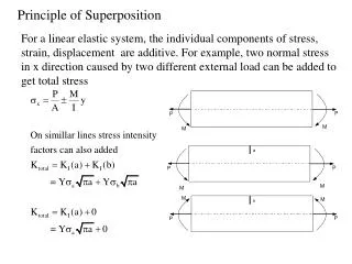
Principle of Engineering ENG2301. Mechanics Section Textbook : A Foundation Course in Statics and Dynamics Addison Wesley Longman 1997. Syllabus Overview. A Statics B Dynamics. Units. force Newton (N) stress Newton per metre squared (N/m 2 )

E N D
Principle of Engineering ENG2301 • Mechanics Section • Textbook: • A Foundation Course in Statics and Dynamics • Addison Wesley Longman 1997
Syllabus Overview • A Statics • B Dynamics
Units • force Newton (N) • stress Newton per metre squared (N/m2 ) • or Pascal, 1 Pa = 1 N/m2 (Pa) • pressure Newton per metre squared (N/m2 ) • or bar, 1 bar = 1x10⁵ N/m2 (bar) • moment, torque, couple • Newton . Metre (Nm)
Units • Most commonly used prefixes • micro x 10-6 • milli x 10-3 m • kilo x 103 k • mega x 106 M • giga x 109 G • * Note Capitals and lower case letters are important
Scalars and Vector • Two kind of quantities: • Scalar • Vector • Scalar quantities have magnitude but no directional properties • can be handled by ordinary algebra, e.g. c= a+b, c= 8 if a=3, b= 5 • e.g. time, mass, speed and energy etc. etc....
l Vector • Associated with directions and magnitude • e.g. Force, displacement, acceleration and velocity • Can be represented by a straight line with arrowhead and the magnitude is shown by the length
Vector Addition and Subtraction • By Triangle or Parallelogram laws • Addition • V = V1 + V2V is called the resultant vector
Vector Addition and Subtraction • Subtraction • V’ = V1 - V2can be regarded as V’ = V1 + (- V2) • - V2is drawn in the opposite directionV’ is the resultant vector
Vector Addition and Subtraction • Adding more than two vectors • V’ = V1 + V2 +V3+V4
Resolution of Vectors • Any vector can be resolved into components • Commonly resolve into two components perpendicular to each other • V = Vx + Vy • Vx = V cos • Vy = V sin • magnitude V = Vx2+ Vy2) • = tan-1 (Vy /Vx )
Force and Newton’s First Law • First Law - If the resultant force acting on a particle is zero, the particle will remain at rest (if originally at rest), or will move with constant speed in a straight line (if originally in motion). • State of Equilibrium - Equilibriumexists when all the forces on a particle are in balance. The velocity of a particle does not change , if the particle is in Equilibrium .
Interpretation of First Law • A body is in Equilibrium if it moves with constant velocity. A body at rest is a special case of constant velocity i.e. v = 0 = constant. • For a body to be in Equilibrium the resultant force (meaning the vector addition of all the forces) acting on the body must be zero. • A Force can be defined as 'that which tends to cause a particle to accelerate', assuming that the force is not in Equilibrium with other forces acting on the body.
Force • A force cannot be seen, only the effect of a force on a body may be seen. • Force Units: S.I. Unit ,Newton, (N) or (kN) • Force is a vector quantity. It has both magnitude and direction.
Force Vectors • Polar and Rectangular Coordinates
Example 1 • Calculate the components in rectangular coordinates of the 600 N force. • Solution
Example 2 • A force vector has the components 600 kN and 300 kN in the x and y directions respectively, calculate the components in polar coordinates. • Solution
Resultant Force • Parallelogram Method
Resultant Force • Algebraic Method
Resultant Force • Triangle of Forces Method Order is not important
Example 3 • Find the magnitude and direction of the resultant (i.e. in polar coordinates) of the two forces shown in the diagram, • a) Using the Parallelogram Method • b) Using the Triangle of Forces Method • c) Using the algebraic calculation method • Solution
Example 3 (Solution) Or -108.260 from +ve x axis
Equilibrium of Concurrent forces Equilibrant E are equal and opposite to Resultant R E = -R
Conditions for Equilibrium • Coplanar: all forces being in the same plane (e.g.only x-y plane, no forces in z direction) • Concurrent: all forces acting at the same point (particle) For three forces acting on a particle
Some Definitions • Particle is a material body whose linear dimensions are small enough to be irrelevant • Rigid Body is a body that does not deform (change shape) as a result of the forces acting on it .
Polygon of Forces • Equilibrium under multiple forces Rigid body under concurrent forces Forces acting on particle
Resultant and Equilibrant Resultant = - Equilibrant R = - F5
Example 4 • The diagram shows three forces acting on a particle . • Find the equilibrant by drawing the polygon of forces.
The forces of action and reaction between bodies in contact have the same magnitude, but opposite in direction. Newton’s Third Law
Free Body Diagram • Free Body Diagram - used to describe the system of forces acting on a body when considered in isolation R R mg R R
System of Particles or BodiesTwo or more bodies or particles connected together are referred to as a system of bodies or particles.External ForceExternal forces are all the forces acting on a body defined as a free body or free system of bodies, including the actions due to other bodies and the reactionsdue tosupports.
Load and Reaction • Loads are forces that are applied to bodies or systems of bodies. • Reactions at points supporting bodies are a consequence of the loads applied to a body and the equilibrium of a body.
Tensile and Compressive Forces Push on the body which is called a compressive force Pull on a body which is called a tensile force
Procedure for drawing a free body diagram • Step 1: Imagine the particle to be isolated or cut “free from its surroundings. Draw or sketch its outlined shape. • Step 2: Indicate on this sketch all the forces that act on the particle. These forces can be applied surface forces,reaction forces and/or force of attraction.
Procedure for drawing a free body diagram • Step 3: The forces that known should be labeled with their proper magnitudes and directions. Letters are used to represent the magnitudes and directions of forces that unknown.
Example 6 (Solution) • resultant R of the two forces in tow ropes No.1 & No. 2 from the components in the x and y directions:
Example 6 (Solution) Equilibrant E = - R
Example 6 (Solution) Resultant R is the sum of the actions of the tow ropes on the barge E = - R Equilibrant E is the reaction of the barge to the ropes
Moment and Couple • Moment of Force • Moment M of the force F about the point O is defined as:M = F dwhere d is the perpendicular distance from O to F • Moment is directional
Moment and Couple Moment = Force x Perpendicular Distance
Resultant of A System of Forces • An arbitrary body subjected to a number of forces F1, F2& F3. • Resultant R = F1 + F2 + F3 • ComponentsRx = F1x + F2x + F3xRy = F1y + F2y + F3y
Resultant of A System of Forces • Resultant moment Mo= Sum of Moments • Mo = F1 d1 + F2 d2 + F3 d3 • Mo = R d
Couple • For a Couple • R =F = 0 • But Mo 0 • Mo = F(d+l) - Fl = Fd • Moment of couple is the same about every point in its plane
Calculate the total (resultant) moment on the body. Example 7
Taking moments about the corner A Note that the forces form two couples or pure moments 3.6 Nm and 3.0 Nm (resultant force =0, moment is the same about any point). Example 7 (Solution)