Download
1 / 14
160 likes | 394 Vues
AMCOM MK66 guidance system. 11-18-2004. System interface specifications. Rocket management system (Target acquisition system on helicopter) IMU GPS Actuator system control Controller I/O bus. Rocket management system.

E N D
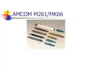
AMCOM MK66 guidance system 11-18-2004
System interface specifications • Rocket management system • (Target acquisition system on helicopter) • IMU • GPS • Actuator system control • Controller I/O bus
Rocket management system • Current system uses analog line for purposes of charging a timing capacitor • Proposed implementation of an RS-232 digital serial interface • RS-232 allows for target data transfer at comfortable data rates, from 300bps to 115200bps. • Standard 9600bps baud rate will more than likely suffice
Rocket management system (cont’d) • RS-232 implementation at 12V active-low • Allows for extended serial cable lengths • Allows for debugging based on a PC serial port using 12V active-low • PC may be used in conjunction with Matlab, C or other to simulate rocket management system outputs • Data format based on target data: • Current position and elevation • Target position and elevation • Current speed • Guidance module returns “target acquired” signal
IMU • IMUs may provide analog or digital outputs; IMUs that we have researched mostly output serial digital signals • 2-wire serial outputs, 5V TTL to Altera serial I/O line • Standard to be defined • I/O types: • Δv, Δθ • 9600bps transmission rate allows more than 8 times the necessary data rate for 16 corrections/second
GPS • Digital serial I/O lines • Provides P(x, y, z), ΔP(x, y, z) • 5VDC (TTL-level power), no voltage division required • Data transmission rate at 9600bps will allow for more than 8 times the necessary data rate for 16 corrections/sec
Altera Cyclone system buses • Memory R/W/ADDR bus, 16MB system memory (SDRAM), interface specifications allow for SDRAM • SDRAM in PC100 specification, managed by onboard memory controller • Local serial, parallel buses • Actuator control: • Via parallel ports, can be used in conjunction with LM741/MIL741 and transistor drivers coupled to relays to trigger actuator assemblies • ADC ICs provide actuator position feedback, 8-bit parallel port solution for feedback to FPGA controller • System clock rates allow for 50MHz modulation (more than enough)
ser. GPS RMS 3 3 RS232 Actuator Control Cyclone ser. 4 ADC 3 IMU Feedback n 8 par. SDRAM PC100
Additional FPGA considerations • Nios devel. kit has two serial ports; three are required for this application: • The RMS and IMU or GPS ports may be shared and appropriately multiplexed • Actuators: • 8-bit parallel port can be set to drive actuator driver circuit. • 8-bit parallel ports (4) will be used for feedback purposes from each servo with ΔV coming from an ADC
Force Resisting Canard Deployment • Force acting on the canard due to acceleration of 80g’s is 42.7N (10 lb) acting on the centroid. (assuming canard dimensions in diagram) • This relates to a torque of 2.7225 Nm • To open the canards with a force applied 1 in from the pivot point, a force of 106.75N (24lb) is needed • This force is possibly to large to produce within the design limitations (space and weight)
Optional Canard Deployments 2. Different Shapes 1. Suicide
NACA Airfoil • 4 digit airfoil • Example: 2412 • Max chamber 0.02c • Camber max location 0.4c • Max thickness 0.12c
Simulation: Upcoming Goals • Researching and understanding DATCOM • Locating Aerospace Block Set and learning the software • Analyzing various fin geometries • Creating new deployment mechanisms