Download
1 / 86
910 likes | 1.25k Vues
Agenda for Design Activity. 1. Objective 2. Design concepts 3. A design process 4. Optimizing design 5. Example 6. Other design processes 7. Homework. 1. Objective. Design activity Product-based activities Products used to manage Completion criteria. 1. Objective. Design Activity.

E N D
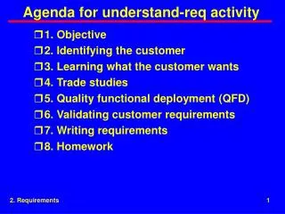
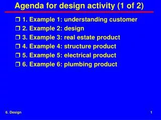
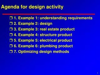
Agenda for Design Activity • 1. Objective • 2. Design concepts • 3. A design process • 4. Optimizing design • 5. Example • 6. Other design processes • 7. Homework
1. Objective • Design activity • Product-based activities • Products used to manage • Completion criteria 1. Objective
Design Activity • The design activity produces a plan defining how the product is to be built and specifying the lower products from which the product is to be constructed. 1. Objective
Design Tasks approval approval Preliminary design review Critical design review spec & I/Fs Develop product concept concept Develop product design design lower specs & I/Fs Develop lower specs & interfaces 1. Objective
Completion Criteria • Design documented to the point that someone else can acquire lower parts, build, test, and sell off the product 1. Objective
Pseudo Completion Criteria • Critical design review is complete 1. Objective
2. Design Concepts • Source of requirements • Goal of design 2. Design concepts
Source of Requirements • Design context • Design Vs requirements • Pseudo customers guiding design • Example pseudo customers 2. Design concepts
Design Context Level N Spec Level N Design Level N+1 Spec 1 Level N+1 Spec 2 Level N+1 Spec M Level N+1 Design 1 Level N+1 Design 2 Level N+1 Design M Level N+2 Spec 1 Level N+2 Spec 2 Level N+2 Spec P Design occurs at each level and produces lower specs 2. Design concepts
Design Vs Requirements Level N Spec Design as seen by level N Level N Design Level N+1 Spec 1 Level N+1 Spec 2 Level N+1 Spec M Requirements as seen by level N+1 Design at level N becomes requirements at level N+1 2. Design concepts
Pseudo Customers Guiding Design Level N Spec Level N Design Pseudo Customers Level N+1 Spec 1 Level N+1 Spec 2 Level N+1 Spec M Pseudo customers guide design in addition to higher-level requirements. 2. Design concepts
Pseudo Customers • Enterprise • Other customers • Development process • Other stakeholders 2. Design concepts
Goal of Design • Meeting all customer requirements • Meeting all pseudo customer requirements • Making the product work 2. Design concepts
Meeting All Customer Requirements • Customer requirements documented in the spec & interfaces from the higher product • Work is guided by the SOW from the higher product 2. Design concepts
Meeting All Pseudo-Customer Requirements • Documented as part of design • Imposed on the product as a black box 2. Design concepts
Making the Product Work • Making the product work includes adding all those features necessary to make the system work including such things as • Form and fit • Turning the product on • Loading the product • Testing the product • Providing build and test features • Interacting with operators 2. Design concepts
3. A Design Process • Conceptualization • Characterization • Preliminary Design Review (PDR) • Critical Design Review (CDR) • Documenting the design 3. A design process
Design Tasks approval approval PDR CDR Preliminary design review Critical design review spec & I/Fs Conceptualization Develop product concept concept Develop product design design lower specs & I/Fs Develop lower specs & interfaces Characterization
Conceptualization • The act of conceiving a notion of what the product is and how it will be built. • Output is the concept, which gives a high-level description of the product sufficient for planning and guiding the design. 3. A design process
Variety of Design Radio House Airplane Telephone Car Design is difficult to describe as a process because details depend upon many factors such as experience and nature of product 3. A design process
Characterization • Converting the concept into the design. • Output is the documented design, which specifies lower products and guides building the product. • Goal to ensure requirements are met & product works 3. A design process
Parallel Characterization Tasks • Partitioning • Making the product work • Allocating design requirements customer & pseudo customer black-box requirements characterization Partitioning Making the product work Allocating design requirements 3. A design process
Partitioning • Dividing the product into lower products • Many reasons for dividing the product may exist 3. A design process
Partitioning Requirements • Need to build • Feasibility • Contractual arrangements 3. A design process
Partitioning Criteria • Similarity to something done before • Cost • Schedule • Performance • Reusability and COTS • Functional cohesion and uncoupling 3. A design process
Partitioning Completion Criteria • Partitioning criteria satisfied • Team consensus • Preliminary design review (pseudo criteria) 3. A design process
Making Product Work Requirements Physical diagram Making product work Functional diagram Concept Data diagram Performance Control Theory of operation Life cycle use Other techniques Making the product work is the result of applying several techniques in parallel.
Requirements Performance Electromagnetic radiation Physical constraints Workmanship Reliability Interchangeability Maintainability Safety Deployability Requirements Human factors Availability Producibility Environmental conditions System security Transportability Computer resources Materials, processes, parts Personnel & training Logistics
Physical Diagram Fin Airframe GPS Motor Warhead Processor Sensor Navigation Fin 3. A design process
Functional Diagram position Determine missile position prediction target location imagery Predict target location Extract target from image Collect imagery Steer missile Determine attitude attitude 3. A design process
Functional Flow Block Diagrams Initialize Start motor 1.0 2.0 Guide during initial phase Guide during midcourse Guide during terminal 3.0 4.0 5.0 Impact 6.0 Functional flow block diagrams (FFBDs)provide time sequences. FFBDs can be hierarchical and many FFBDs are needed to define a product 3. A design process
Data Diagram Determine missile position position target location prediction imagery Predict target location Extract target from image Steer missile Collect imagery Determine attitude attitude 3. A design process
Performance Midcourse Terminal Impact Initial Accuracy Range Range Launch Accuracy Weight & cost Performance parameters may influence design 3. A design process
Logical Control • Selects from among a finite set of discrete options • Power control • Initialization • Loading control • Configuration control • Test Vs operation selection • Control of operation 3. A design process
State Variable Control • Continuous within the bounds of measurement resolution • Flight control • Process control 3. A design process
State and Status • State -- a condition the system is in • Status -- another word for “state”, often used to indicate health • If the words “state” and “status” are both used in a design, a clear definition of when each word applies reduces confusion • Using the words “state” or “status” with an adjective also reduces confusion; e.g., power state, failure status 3. A design process
Modes • Mode -- a manner of acting; often used interchangeably with the word “state” • If the words “state” and “mode” are both used in a design, a clear definition of when each word applies reduces confusion • Using the words “state” or “mode” with an adjective also reduces confusion; e.g., power state, transmit mode 3. A design process
Reconfiguration • Choosing from redundant elements; e.g.., transmit channels, power supplies, engines • Increases the operation time between repairs 3. A design process
Reconfiguration Justification • Need reason for expensive in design and test • Customer requirements such as preference or mean time between critical failure • We can, it’s more elegant, or we can’t say no to ourselves 3. A design process
Other Techniques • Theory of Operation -- A tutorial description of the way the product operates. This tutorial should describe operation during the complete life cycle • Life Cycle Use -- A timeline showing the most common use of the product in each phase of its life. 3. A design process
Allocating Design Requirements • Flowdown • Flowdown and design studies 3. A design process
Flowdown Level N Spec Flowdown Level N Design Pseudo Customers Level N+1 Spec 1 Level N+1 Spec 2 Level N+1 Spec M Level N+1 Test Equip Level N+1 Interfaces SOWS Flow down from requirements to design to lower specs, interfaces, and SOWs 3. A design process
Flowdown and Design Studies spec Verification by analysis design study Design Verification capture FCA lower spec 1 lower spec 2 configuration management Design studies used to expand requirements or to handle requirements verified by analysis need to be captured for use in verification by analysis, verification, and PCA 3. A design process
PDR • Performed when approach is established • Objective -- design headed in right direction • Determines • Approach will work • Designers understand customer & requirements • Top-level diagrams available • Theory of operation understood • Design covers all program phases • Risk 3. A design process
CDR • Performed when product is ready for build • Objective -- design complete • Determines • Design covers all program phases • Risk • Design can be tested • Lower products & I/Fs specified and compatible 3. A design process
Design Documentation Files within a file manager Files within an intranet Data base Method Paper Understandable 10 9 7 8 Electronic no yes yes yes Easy to enter data 7 10 7 10 Easy to view data 10 9 3 10 Easy to keep current 3 10 7 9 Easy to correct 3 10 7 10 Easy to navigate 6 8 3 10 Easy to capture design 5 10 3 10 Acceptability 10 9 5 8 Design needs to be documented to the point the product can be built and tested. Several method exist. Intranet is becoming popular
4. Optimizing Design • Waterfall process • Modified waterfall process • Providing information when needed 4. Optimizing design
Waterfall Process System design System i&t Box design Box i&t Software design Software i&t Waterfall process has classic V pattern. Steps are serial with each step finishing before the next starts 4. Optimizing design
Modified Waterfall Process Tasks start earlier System design System i&t Box design Box i&t Software design Software i&t Software and box developed in multiple builds Modified waterfall process has shorter cycle time because it starts tasks earlier and allows tasks to develop in parallel through techniques such as multiple builds. 4. Optimizing design
Providing Information when Needed Percent of requirements complete 100 0 0 100 Percent of tasks to be developed Concept Functions I/Fs Mechanical Test Development can start before requirements are complete 4. Optimizing design