Download

1 / 59
610 likes | 979 Vues
4.4.1.6- SPARE PARTS. TM60 SPARE PARTS: TRANSMITTER (P.B.). PS60/1 SM upper part. TM60 SPARE PARTS: TRANSMITTER (P.B.). PS60/1 upper part. TM60 SPARE PARTS: TRANSMITTER (P.B.). PI60/1 lower part. TM60 SPARE PARTS: TRANSMITTER (P.B.). LE61 logic board. TM60 SPARE PARTS: TRANSMITTER (P.B.).

E N D
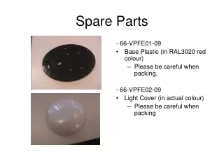
TM60 SPARE PARTS: TRANSMITTER (P.B.) PS60/1 SM upper part
TM60 SPARE PARTS: TRANSMITTER (P.B.) PS60/1 upper part
TM60 SPARE PARTS: TRANSMITTER (P.B.) PI60/1 lower part
TM60 SPARE PARTS: TRANSMITTER (P.B.) LE61 logic board
TM60 SPARE PARTS: TRANSMITTER (P.B.) PS60/2 SM upper part
TM60 SPARE PARTS: TRANSMITTER (P.B.) PS60/2 upper part
TM60 SPARE PARTS: TRANSMITTER (P.B.) PI60/2 lower part
TM60 SPARE PARTS: TRANSMITTER (P.B.) LE62 logic board
TM60 SPARE PARTS: TRANSMITTER (P.B.) TD450 radio
TD450 POWER SELECTION Power selection R19 C62 C64 C61 C63 - In order to modify the power, modify the R19 resistor value. - Low power: remove the R19 resistor. - medium power: use a 470 K resistor (standard). - High power: use a 15 K resistor.
TD450 QUARTZ MODIFICATION From June of the year 2003, all the manufactured radios, they are manufactured with the quartz crystal in vertical position. In the Technical Assistance Service also, besides repairing the TD450 radios, they modify it placing the quartz crystal in vertical position. This change is due to the falling tests we made from on meter high; after 700 falls, the quartz crystal continued without breaking and until the time being, we didn’t receive any broken TD450 with the quartz crystal in vertical position. NOTE: It happens that from time to time we receive TD450 radio units with other mark quartz crystal. We remind you that the only homologated quartz crystal from our R+D department is the QT quartz crystal. We made tests with other quartz crystals, and they broke very fast or the frequency moved with a temperature change. Do not use other type of quartz crystals. Quartz crystal MODIFICATION: We make a hole in the PCB. The quartz crystal is introduced, so that the sideburns and the encapsulation doesn’t touch the radio covers and it gets fixed to the PCB getting welded in the lower face of the PCB. We bend the sideburns so that they don't touch the encapsulation of the quartz crystal and they are welded to their corresponding points of welding in the upper face of the PCB. Upper face
TM60 SPARE PARTS: TRANSMITTER (P.B.) P60 Push button CP60 Push button cover
TM60 SPARE PARTS: TRANSMITTER (P.B.) M60 Spring return switch S60 Maintained switch
TM60 SPARE PARTS: TRANSMITTER (P.B.) K60 Key switch EMS60 Stop push button
TM60 SPARE PARTS: TRANSMITTER (P.B.) BT06 Battery
TM60 SPARE PARTS: TRANSMITTER (P.B.) B60 strap
TM60 SPARE PARTS: TRANSMITTER (C.B.) PS60/3 upper part (personalised)
TM60 SPARE PARTS: TRANSMITTER (C.B.) Handle TM70/3
TM60 SPARE PARTS: TRANSMITTER (C.B.) PI60/3 lower part
TM60 SPARE PARTS: TRANSMITTER (C.B.) LE63 logic board
TM60 SPARE PARTS: TRANSMITTER (C.B.) PS60/4 upper part (personalised)
TM60 SPARE PARTS: TRANSMITTER (C.B.) Handle TM70/4
TM60 SPARE PARTS: TRANSMITTER (C.B.) PI60/4 lower part
TM60 SPARE PARTS: TRANSMITTER (C.B.) LE64 logic board
TM60 SPARE PARTS: TRANSMITTER (C.B.) TD450 radio board
TD450 POWER SELECTION Power selection R19 C62 C64 C61 C63 - In order to modify the power, modify the R19 resistor value. - Low power: remove the R19 resistor. - medium power: use a 470 K resistor (standard). - High power: use a 15 K resistor.
TD450 QUARTZ MODIFICATION From June of the year 2003, all the manufactured radios, they are manufactured with the quartz crystal in vertical position. In the Technical Assistance Service also, besides repairing the TD450 radios, they modify it placing the quartz crystal in vertical position. This change is due to the falling tests we made from on meter high; after 700 falls, the quartz crystal continued without breaking and until the time being, we didn’t receive any broken TD450 with the quartz crystal in vertical position. NOTE: It happens that from time to time we receive TD450 radio units with other mark quartz crystal. We remind you that the only homologated quartz crystal from our R+D department is the QT quartz crystal. We made tests with other quartz crystals, and they broke very fast or the frequency moved with a temperature change. Do not use other type of quartz crystals. Quartz crystal MODIFICATION: We make a hole in the PCB. The quartz crystal is introduced, so that the sideburns and the encapsulation doesn’t touch the radio covers and it gets fixed to the PCB getting welded in the lower face of the PCB. We bend the sideburns so that they don't touch the encapsulation of the quartz crystal and they are welded to their corresponding points of welding in the upper face of the PCB. Upper face
TM60 SPARE PARTS: TRANSMITTER (C.B.) MO60 optical joystick (with the cover) • Programable steps: 1,2,3,4,5 or Stepless. • Stepless: Resolution 16 steps per sense.
Place between mechanical part and PCB plastic washes (code 1133021) in each attachment screw. MO60 PERSONALIZATION There are some MO60 that has a Dead Man push button. This push button is used as Dead Man of the controller or to send an independent manoeuvre by the P2 connector. In the first case the cables coming from the push button are connected to HM and in the second case they are connected to ORD. In the standard applications (those that do not have Dead Man push button) the HM must be bridged and ORD without bridge. If when replacing a MO60 by another one we copy the configuration of the bridges, we will avoid to consult personalization table. S HM Vertical Cover selection: 0 for open cover 1 for cross or line cover E O Horizontal ORD N 1 2 3 P3 0 0 0 0 1 1 1 1 Vertical axis selection D2 D1 P2 0 0 0 Horizontal axis selection 1 1 1 Weld point The MO60 is an optical controller that can govern a maximum of 32 steps for each sense (North, South, East and West) in two-way perpendicular senses (Vertical and Horizontal).The number of steps of each sense in each direction can be personalized by welds in the electronic circuit according to table 1. It consists on two parts: one electronic in which we personalize the steps and the other a mechanical part. The mechanical one has 6 different arms with 1, 2, 3, 4, 5 steps or continuous (stepless). The steps of the mechanical arms have to correspond with the electronic steps. With the MO60 we can act in diagonal, acting in two-way senses simultaneously (open cover). If we do not want to works in diagonal, besides to personalize it with welds in the electronic circuit, we must place a cross cover or a horizontal or vertical line cover for each way of work (table 2). For repairs on field, as we cannot have spare parts of MO60 with all the possible combinations, we recommend to have one with continuous arms. We can personalize the corresponding steps electronically and the MO60 will work normal but without noticing the speed changes by the user. The adjustment of the mechanics with the electronic card is very critic, that’s the reason why it is not advisable to interchange cards with different mechanical parts. When replacing a MO60 always replace the complete MO60 (the mechanics along with its corresponding card). 3 2 1 MODE 1 STEP 0 0 1 WITHOUT CROSS (Works in diagonal) 0 2 STEPS 0 1 0 WITH CROSS (Doesn’t work in diagonal) 1 3 STEPS 0 1 1 LINEAL (Only works in one direction) 1 4 STEPS 1 0 0 5 STEPS 1 0 1 STEPLESS 1 1 1 TABLE 1 TABLE 2
TM60 SPARE PARTS: TRANSMITTER (C.B.) • Only one step. Electrical joystick (with the cover)
TM60 SPARE PARTS: TRANSMITTER (C.B.) Analogue joystick • Programable steps: Stepless. • Stepless: Resolution 127 steps per sense.
TM60 SPARE PARTS: TRANSMITTER (C.B.) • Two types: until 6 steps (programable) Optional: 12 steps (programable) • Includes two independent circuits Digital rotary switch
ROTARY SWITCH PERSONALIZATION How to personalize the steps: 1º Return the rotary switch left until reaching the end in position “0” 2º Take out the end located in hole Nº 4 Fix end in “0” position (don’t remove it) 3º Insert the end in the corresponding hole to obtain different steps 0 1 2 3 For 2 positions, insert the end in Nº 4 4 5 For 3 positions, insert the end in Nº 6 6 M For 4 positions, insert the end in Nº 8 7 8 For 5 positions, insert the end in Nº 10 9 10 For 6 positions, insert the end in Nº 11 11 12
TM60 SPARE PARTS: TRANSMITTER (C.B.) 0-1 push button (with the cover)
TM60 SPARE PARTS: TRANSMITTER (C.B.) 0-1 maintained switch (with the cover) 1-0-1 maintained switch (with the cover) 0-1 spring return switch (with the cover) 1-0-1 spring return switch (with the cover)
TM60 SPARE PARTS: TRANSMITTER (C.B.) K60P Key switch 311 Key switch
TM60 SPARE PARTS: TRANSMITTER (C.B.) Stop push button
TM60 SPARE PARTS: TRANSMITTER (C.B.) BT12 Battery
TM60 SPARE PARTS: TRANSMITTER (C.B.) C60C Belt
TM60 SPARE PARTS: RECEIVER Low cover receiver box
TM60 SPARE PARTS: RECEIVER High cover receiver box
TM60 SPARE PARTS: RECEIVER LR61 logic board
TM60 SPARE PARTS: RECEIVER LR62 logic board (to be used with expansions)
TM60 SPARE PARTS: RECEIVER OU609 relay board
TM60 SPARE PARTS: RECEIVER OU609/DC relay board
TM60 SPARE PARTS: RECEIVER OU618 relay board
TM60 SPARE PARTS: RECEIVER OU618/DC relay board
TM60 SPARE PARTS: RECEIVER R20 expansion board
TM60 SPARE PARTS: RECEIVER R20/DC expansion board