Download
1 / 31
320 likes | 572 Vues
The LHCb VELO Upgrade. Jianchun Wang Syracuse University For the LHCb VELO Group VERTEX 2009 Workshop,Veluwe, Netherlands, Sept 13-18, 2009. The LHCb Environment. b. doesn’t occur. b. b. b. b. b. A dedicated b-physics experiment.

E N D
The LHCb VELO Upgrade Jianchun Wang Syracuse University For the LHCb VELO Group VERTEX 2009 Workshop,Veluwe, Netherlands, Sept 13-18, 2009
The LHCb Environment b doesn’t occur b b b b b A dedicated b-physics experiment • Designed to maximize B-acceptance within cost and space constraints. • Forward spectrometer ( 1.9 < |h| < 4.9 ), where b are maximally boosted, benefits proper time measurement. • One arm is OK since bb directions are correlated. • Production sbb~500 mb, Min. bias: sinel ~ 80 mb. • Choose to run at <L>~21032 cm–2s–1(2 fb–1/year),~1012 bb pairs produced per year. • Maximize probability of single interaction per crossing. • Clean environment (average interactions per crossing <n>~ 0.5 ), easier to reconstruct. • Less radiation damage ( the closest tip ~7 mm away from beam). Jianchun Wang, Vertex 2009
The LHCb Detector • VErtex LOcator • primary vertex • impact parameter • displaced vertex VErtex LOcator Trigger Tracker Tracking Stations Ready to go ! • s(IP) ~ 14 mm + 35 mm / Pt • Primary vertex ~10 mm in X/Y, ~50 mm in Z. • B proper time resolution ~ 40 fs. Jianchun Wang, Vertex 2009
Limitation of Current Trigger System muon trigger hadron trigger • To improve the physics sensitivity LHCb plan to increase the luminosity by a factor of 10. • Current trigger system has two stages: • L0 hardware trigger, reduce to 1 MHz. • HLT software trigger, reduce to 2 kHz. • L0 trigger limit is driven by 1 MHz maximum readout rate. Rate • With increased L, the L0 criteria has to be tighten to stay below 1 MHz. There is not much net gain, especially in hadron channel. • Increasing L to 1033 will not introduce too much complexity to event. Most events have 1 or 2 interactions. Increasing to 2x1033 the average number of interactions increases to ~ 4, • At L=2x1033, unacceptable increase in CPU time due to large combinatorics. Jianchun Wang, Vertex 2009
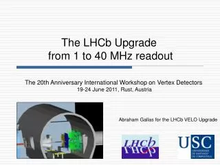
LHCb Upgrade Strategy • Run at 2x1033 cm-2s-1 for 5 years (~100 fb-1). This plan is consistent with, but independent of the sLHC upgrade program. • LHCb will readout all sub-detectors at 40 MHz replace FE electronics of most detectors. • The trigger decision will be performed entirely on CPU farm. • Removing L0 trigger, thus no limit on the data rate. • Software trigger allows sophisticated triggering scheme with lower Pt cuts and use of IP to maximize the signal yields. • Preliminary studies show that at current L the hadronic channel efficiency improves by ~2 (the goal), and the yield increases proportionally to L. • Increases in statistics by ~20 for hadronic channels and ~10 for leptonic channels. • More complicated events significantly increase trigger processing time, increasing granularity is mandatory. • Improve or maintain efficiency and resolution. Jianchun Wang, Vertex 2009
Current Vertex Locator ~ 1 m RF foil 3cm separation interaction point pile-up veto (R-sensors) • Silicon micro-strip, n+ in n-bulk sensors. • Detector halves retractable (by 30mm) for injection. • 21 tracking stationsper side. • R-Φ geometry, 40–100μm pitch, 300mm thickness. • Optimized for • tracking of particles originating from beam-beam interactions. • fast online 2D (R-z) tracking. • fast offline 3D tracking in two steps (R-z then f). r=42 mm r=8 mm ( ~7 mm) 2048 strips Jianchun Wang, Vertex 2009
Current VELO Detector for Upgrade? Start upgrade studies from the current VELO • At L=2x1033 the occupancy will be high, especially at the inner region (particle/hit occupancy ~2%, strip occupancy ~4%). Higher granularity and lower noise are needed. Pixel architecture meets the need. • Analog readout of VELO data at 40MHz is unrealistic. Signals need to be digitized and sparsified at FE. • The data rates are enormous. Clustering reduces the data rates out of FE. • This triggered a dedicated R&D on radiation hard FPGAs. • Pixel architecture reduces pattern recognition difficulty. Particle Hits / Event / cm2 Inner Radius Radius (cm) Fit to aRb Jianchun Wang, Vertex 2009
Pixel Detector • Two main thrusts of R&D required for the upgrade are: • Front-End Electronics • Sensor • We had studied different types of sensors and readout schemes. We decide to focus on an upgrade solution based on pixel architecture. Jianchun Wang, Vertex 2009
Front-end Electronics Jianchun Wang, Vertex 2009 • Must provide digitized data to trigger processor in real time: digitization, data sparsification, and pushing data to storage buffer. • Withstand same radiation environment as sensor TID: ~400 MRad. • Modern fabrication technologies may allow larger radiation tolerance – 130 nm, 90 nm. • Issues to be investigated • Analog electronics optimization: noise, peaking time, stability of performance with irradiation, leakage current compensation • Digitization: speed, effective number of bits. • Zero suppression: effective threshold, time walk, discriminator stability • Digital section: data rate capability, stability of performance with irradiation.
Timepix Readout Chip Q 14100 14100 Medipix3 Chip dimensions 800 See Richard Plackett’s presentation for more details Comparator threshold Comparator output LE TE ToT = TE - LE Pixel readout chip based on Medipix2 256 x 256 pixels 55 mm square, and chip is 3 side buttable. Single Layer Modules Possible!! (X0) By using TSV (through silicon vias) dead side can be reduced to 0.8 mm in Medipix3 (out of 1.5 mm) Analogue power consumption 6 mW per pixel. TOT provides better than 6 bit equivalent ADC resolution Upgrade being considered to 90 nm technology (power consumption, density of logic and radiation hardness benefits) Specifications for Timepix adaptation to VELO upgrade needs are under study. Jianchun Wang, Vertex 2009
Conceptual Design Beam position Ground plane (aluminised directly onto diamond) Diamond thermal plane with cutouts immediately above TSV regions Silicon (1-3 pieces) 55x55 mm pixels + 800 mm pixels in areas under chip periphery 10 Tiimepix chips (periphery indicated in white) Power strips and signal routing area Cooling channel Advantage: Single layer, less material, very important for IP. Challenges: power tape + TSV, Thinned electronics / sensor. Cross section cutout region Jianchun Wang, Vertex 2009
Timepix In Real Beam DUT 6 plane Timepix/Medipix telescope Track reconstructed A telescope was constructed with 6 double rotated (9o) around both axes. 4 Timepix and 2 Medipix sensors were used. The DUT (in this case another Timepix chip) position and angle are controlled by a stepper motor to reduce the number of interventions Jianchun Wang, Vertex 2009
Quick Look at TimePix Testbeam Data Indiv. pixel Normal Incidence All N=1 N=2 Unbiased Residual (mm) N=3 N=4 Angle (Degree) Total Charge N=2 (Npixel=N) / All N=1 N=3 N=4 Angle (Degree) More to Be Studied • Time walk, which could potentially affect physics. • Non-linear gain curve. • Investigate methods of moving data off chip at required speeds (started, digital processing within pixel array may be necessary). • Testbench features of baseline module. Jianchun Wang, Vertex 2009
Medipix3 X-ray Irradiation Total ionizing dose measurement on a single chip up to 400Mrad (X-ray, continuously over 4 days) Confirmation of previous single transistor studies on 130nm CMOS Chip readout DACs, LVDS etc remained operational for full dose. This needs to be followed up by hadron irradiation. Jianchun Wang, Vertex 2009
75.8% s=11.3 mm Number of Hits (arb Unit) Number of Rows Residual (mm) Pixel X/Y Current VELO Pixel Y Pixel X/Y 5 stations 6 modules per station 4 chips per module Total 120 FPIX2 chips Aperture 35 x 35 mm2 ~ 1 m Jianchun Wang, Vertex 2009
Electronics Development Two main avenues of investigation in LHCb Upgrade FPIX2 • Features (selected): • Derived from BTeV • Columnar architecture (50mm x 400 mm) • Flash ADC (3-bit) • Data driven readout. • Sensor and electronics successfully thinned down to 200 mm. • Separate X/Y precision measurements. Large digital periphery requires overlap material. • Need to Study (selected): • Modern fabrication technology • Radiation hardness study. • Stability of front end electronics • Readout speed, with designed for 132ns. • Cooling. • Focus resources on a single chip development (still useful for sensor R&D). TIMEPIX • Features (selected): • Derived from MediPix • Square pixel (55mm x 55mm) • Time over threshold • Single layer module possible, edgeless possible • Need to Study (selected): • Modern technology: 130nm or 90nm. • Radiation hardness study. • Optimization of analog front end • Time walk • Digitization precision and readout scheme • Data flow and data rate • TSV technology • Detector and sensor thinning • Cooling • Development continues. Jianchun Wang, Vertex 2009
Sensor • Sensor requirements • Radiation hardness • Low leakage current, heat dissipation • High granularity • Minimize material • Sensors investigated: • Sensors of current type: n-type, strips • Sensors with small modifications: p-type • Sensors with large modifications: pixels • Sensors using new technology: 3D • Alternative material: diamond Jianchun Wang, Vertex 2009
Test of Irradiated Sensors Preliminary • VELO sensors of n-type and p-type were differentially irradiated. • They were tested in the beam at Fermilab using FPIX2 pixel system for tracking (in collaboration with Dave Christian). • Irradiation particle flux ~ 0.86x10¹⁵ neq/cm2 (~6 years running of current L at inner radius). • More results on irradiated sensors are coming soon. N type sensor 1 MIP Qmp N-type ~ 25% drop Preliminary Measured in 120 GeV proton beam @ -10C Jianchun Wang, Vertex 2009
Double-sided 3D Sensor Optimisation for SLHC: Nucl. Instr. Meth. A 592 (2008) 16 Glasgow / CNM Test beam results: Nucl. Instr. Meth. A 607 (2009) 89 Pixel on Medipix detector SEM after polysilicon deposition and etching • novel double sided structure • n-bulk and p-bulk detectors produced & tested 9.4mm Jianchun Wang, Vertex 2009
Double-sided 3D Sensor 2.3V lateral depletion ~9V back surface depletion 3D Planar Glasgow / CNM • Measurements of: • Charge loss in holes • Charge sharing • Irradiations • Two presentations at IEEE NSS with full results P+ Tesbeams at Diamond Light Source (X-rays), CERN (MIPs) 3D, 15keV Signal Noise Charge sharing N+ Jianchun Wang, Vertex 2009
Sensor R&D • Diamond sensor • Ultra radiation hard, • Very low leakage current (~nA instead of mA) • Needs no guard ring and can be edgeless. • CVD diamond can also be used as heat conductive spine. • Joined RD42 collaboration for investigate this option. • Planning test beam studies of different solutions. Syracuse/RD50 • P-type silicon sensor • “BTeV style” single chip pixel devices. Fabricated by Micron Semiconductor. • Depletion voltage 20-80V before irradition. • Started examining performance of irradiated detectors Syracuse/RD42 Jianchun Wang, Vertex 2009
MAIN REQUIREMENTS Separates accelerator and detector vacua (must be ultra-high vacuum compatible) Should have the smallest radiation length possible, esp. before first measured point Must shield against RF EMI pick-up effects Must carry beam image charge Must allow for sensor geometry and overlap Must withstand high radiation levels CURRENT DESIGN Foil is 300 um AlMg3, coated with insulator and getter Foil shape set by overlapping sensors, beam clearance and beam effects Wakefield suppressors to adapt beam pipe geometry Was a huge engineering effort (NIKHEF) UPGRADE DESIGN Replace AlMg3 by Carbon Fiber composite Use large-modulus fibers (stiff, low density) Resin with high rad tolerance, low outgassing (space-qualified), micro-crack resistant Produce foil + box + flange as a single integrated unit Avoids sealing problems Can reduce mass thickness to ~50% current Similar material mechanically stable to above 500 MRad (CERN 98-01) Currently in development with industrial partner CMA (Composite Mirror Applications, Inc.) Prototyping planned to start by End 2009, testing to start in early 2010 POSSIBLE NEW RF FOIL for UPGRADE Dominant contribution to the average X0 of particle traversing VELO at 2<h<4.2 CURRENT DESIGN FOIL ~200 mm x 1 m Jianchun Wang, Vertex 2009
Conclusion • The LHCb detector is ready to take data. Initial plan is to collect 10 fb-1 in the first 5 years. • LHCb upgrade forseen for 2015/16, with luminosity increases to 2x1033 cm-2s-1, expected to collect 100 fb -1 in 5 years. • Key aspects of the upgrade are: • Readout of the full detector at 40 MHz fully software-based trigger flexibility. • Improved granularity in sub-detectors needed to cope with larger occupancies, provide better background suppressing and reduce CPU time/event. • Goal is to increase sample sizes by a factor of 10-20 with comparable or better S/B to current detector. • Many R&D projects associated with VELO upgrade are in progress: readout electronics, sensor, hybrid, mechanics, cooling cabling etc. • The VELO upgrade is feasible. Jianchun Wang, Vertex 2009
Backup Mini Strip Plan p-stop or p-spray. Inner radius at 7.5mm, 25-30 mm pitch (edgeless sensors would bring 10% improvement) Double sided module 20 Beetle40 chips 200 mm Diamond heat plane routing out Beetle signals 200 mm thin silicon sensor Radiation length 0.6%. Cooling channel Need to study more on data readout scheme. Jianchun Wang, Vertex 2009
Trigger Time in HLT Di-hadron L = 2 x 1032 cm-2s-1 L = 2 x 1033 cm-2s-1 L = 1 x 1033 cm-2s-1 • At L=2 x 1032 cm-2s-1, the events are more complex. • With current VELO-like detector, the pattern recognition is very slow. And trigger can not be decided within 2.5 mm latency. Jianchun Wang, Vertex 2009
Irradiation Issue Operating up to ~120 fb-1 Flux: 0.8x10¹⁴ neqcm-2 per fb-1 TID (Electronics): 3.7 MRad per fb-1 at tip ~ 7mm • After this dose @ 900V we expect • 102 uA / cm-2 at -25o C • CCE of ~ 8.5 ke- • Thermal runaway at the tip is the issue Dose after 100 fb-1 500 T. Affolder TIPP 09 50 neqcm-2 x 10¹⁶ TID (MRad) 5 Radius (cm) tip of current VELO Jianchun Wang, Vertex 2009
FPIX2 Readout Chip 9.0 mm 0.7 mm 22x400mm 128x50 mm FPIX2 Chip 6.4 mm I/O & Control pads from Chip to HDI 10.3 mm Jianchun Wang, Vertex 2009