Download
1 / 28
290 likes | 473 Vues
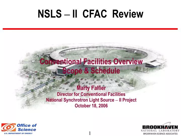
NSLS – II CFAC Review. Conventional Facilities Overview Scope & Schedule Marty Fallier Director for Conventional Facilities National Synchrotron Light Source – II Project October 18, 2006. Outline. Conventional Facilities Scope Facility Overview - CF WBS - Facility Program

E N D
NSLS – II CFAC Review Conventional Facilities Overview Scope & Schedule Marty Fallier Director for Conventional Facilities National Synchrotron Light Source – II Project October 18, 2006
Outline • Conventional Facilities Scope • Facility Overview - CF WBS - Facility Program • Ring Building • Central Lab Office Building • Lab Office Building(s) • Utilities • Schedule • Risks and Challenges
NSLS II Site Plan NSLS Conf. Center Service Bldg Typ 4 CLOB CFN Future JPsi RF-LINAC AREA Future Guest House Ring Bldg LOB Typ 4 Underpass Loading
Ring Building Concept • Divided into 5 clusters • Service Bldg supports all services within the cluster • Six sectors/Cluster • CLOB & Service Bldgs contain all Accelerator systems • Ring, CLOB, LOB 1 & service bldgs are base scope • LOB’s 2,3,4 can be added as needed w/o interruption Area of initial Operations
Tunnel Design • Roof and wall thicknesses generally driven by shielding criteria except inner wall in area of berm (just structural) • Outer wall (ratchet wall) is HD concrete • During T-I will study whether precast or poured in place provides best balance of technical and cost performance • Tunnel floor thickness driven primarily by vibration criteria • Will do modeling to arrive at optimal thickness and section shape • Rigidly connected to exp. floor to create monolithic floor • Penetrations from above for power and cooling water • Penetrations from sidewall for HVAC Supply and Return
Tunnel Access • Egress for life safety achieved by exits at each service building location • Large shielded doors for equipment access provided at Service buildings for tunnel entry • Mandoors and labyrinth provided at each Service building • Vehicle ramp to roll-up door at 2nd floor of each Service Bldg provides equipment access to electrical mezzanine at top of tunnel • RF & LINAC areas integrated with CLOB structure have similar access as Service Bldgs
CLOB Features • Space for 190 Offices, 8 labs • Nominally 30 User Offices, 5 User labs from the total • Possible 400 seat Conference Center addition w/ vendor area and three breakout rooms • Lobby and User Reception area • 2nd floor viewing gallery overlooking experimental floor • Bridge to electrical mezzanine and control room & RF/LINAC areas • Close Proximity to future: • JPSI Building • Guest house
LOB Features • Modular design – can be added when needed without interrupting operation • 11,000 SF each – Serves six sectors • 30 offices w/ conference space, interaction areas, lavs, showers • 5 labs intended for shared use • Shipping/Receiving/Storage area & chemical storage area • Potential for expansion for more offices if needed • Egress provided for personnel and large items at each LOB • Loading area with exterior roll-up door • Roll-up door from each lab onto the experimental floor • Designed to minimize impacts to future long beamlines
Utility Support • Utilities run underground in center of ring and distributed to five service bldgs (one in CLOB RF/LINAC area) • Minimizes pipe runs and pipe size in bldg proper • Only needed service piping will be run in experimental area • Minimizes potential noise and vibration impacts • Services provided at each Beamline include: • Electric Power Panel at Ratchet Wall, 75-95kW/Cell, 120/208V • Cooling Water, HVAC Supply Air, Exhaust • Compressed Air, LN2, GN2 • DI Water (Copper and Aluminum systems) by Accelerator Group
Utility Support • Utilities run underground in center of ring and distributed to five service bldgs (one in CLOB RF/LINAC area) • Minimizes pipe runs and pipe size in bldg proper • Minimizes potential noise and vibration impacts • Mechanical Utilities include: • Chilled water from expansion of Central CHW Plant • Tower water from process cooling water tower • Steam & condensate from Central Steam System • Potable water, compressed air, sanitary to existing mains • Electrical Utilities distributed via substation and load center at each services bldg • Communication/Data via underground BNL F/O network
Schedule • Key schedule objective – Enable start of accelerator installation March 2010 • CF is critical path until the main bldg spaces are turned over for accelerator installation • Cluster areas of Ring bldg to be released for BO in phases • Key durations: • Title I Design – 9 months • Title II Design – 10 months • Site preparation – 6 months • Main bldg contract bid & award – 6 months • Main bldg contract duration 34 months
Schedule FY07 FY08 FY09 FY010 FY11 FY12 Activity FY13 Title I Design CD-2 Title II Design CD-3 Site Preparation Const. Pre-cast Shield Wall Const. Ring Bldg/CLOB/LOB Bid & Award Construction 1st Cluster ready for Accel. installation Ring Bldg BO CHW Plant Expansion Mech & Elect Utilities Integrated Ctrl & Comm. Standard Equipment Commissioning
Risks & Challenges • Technical Challenges • Constructing massive concrete tunnel with reasonable economy • Achieving structural stability • Minimizing differential settlement • Vibration mitigation • Achieving thermal stability – • Tight temperature constraints for tunnel • Assuring interior/exterior thermal gradients don’t affect beam • Making tunnel available for accelerator installation in phases • Risks • Cost sensitivity of achieving all of the above • Volatile material/construction markets