Download
1 / 10
120 likes | 262 Vues
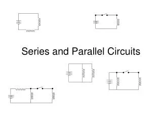
9.1 Series and Parallel Circuits Pg. 306. People here have multiple paths to follow. Series Circuits. Voltage decreases as electrons pass through each load Voltages across each of the loads adds up to the voltage supplied by the source. There’s only one path to follow

E N D
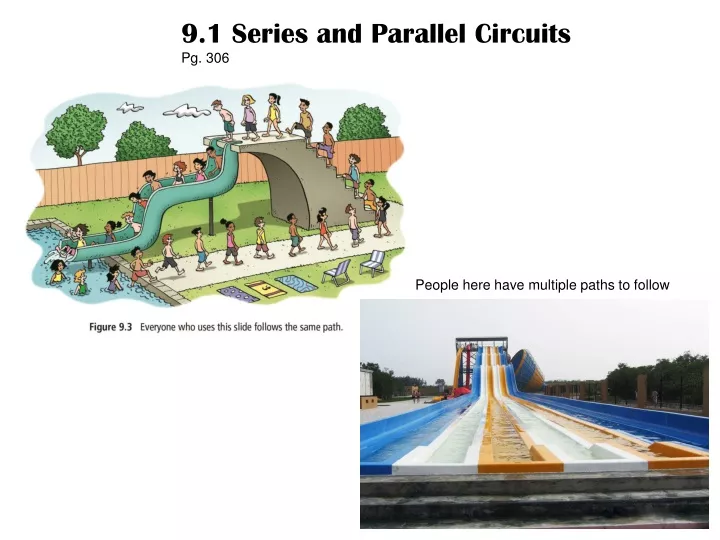
9.1 Series and Parallel Circuits Pg. 306 People here have multiple paths to follow
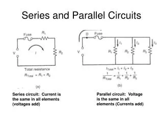
Series Circuits • Voltage decreases as electrons pass through each load • Voltages across each of the loads adds up to the voltage supplied by the source. • There’s only one path to follow • Current is constant throughout the circuit • Resistance of resistors increases when in series • - like more speed bumps in a row
Voltage is the same across each load There’s more than one path to follow Current varies between each pathway, depending on the resistance of the path, but still adds to the total current supplied by the source. Resistance decreases with each added resistor New pathway created thus lowering the total resistance Junction point is where a circuit divides into multiple paths The total current entering a junction point must equal the sum of the current leaving the junction point Parallel Circuits
Find the unknown Voltage (V) and the Current (A) in each of the following circuit diagrams. Voltage = 10.0 VCurrent = 3.0 A Voltage = 12.0 VCurrent = 4.0 A
DRAWING PARALLEL & SERIES CIRCUITS • Draw a circuit diagram consisting of a 9.0 V battery, an ammeter, and a 25 resistor in series. Include a voltmeter that is measuring the potential difference across the resistor. • Draw a circuit diagram consisting of a battery made up of two 1.5 V cells, one closed switch, two lamps, and an ammeter in series. Show the direction in which the current flows. • Draw a circuit diagram consisting of a battery made up of four 1.5 V cells, one closed switch, one lamp, two 0.50 resistors in series, and a voltmeter. Show the direction in which the current flows.
MORE PRACTICE DRAWING PARALLEL & SERIES CIRCUITS Draw a series circuit consisting of: 12 V electrical source open switch two light bulbs 10 resistor Draw a parallel circuit consisting of: 9.0 V electrical source open switch three 5.0 resistors Draw a circuit consisting of: three 1.5 V cells connected in parallel open switch two light bulbs connected in series two 15 resistors connected in parallel
INTERPRETING CIRCUIT DIAGRAMS • Describe what will happen in the circuit shown above if… • (a) the switch is closed • the switch is closed and the first bulb is removed • the switch is closed and the fifth bulb is removed a) Current flows through whole circuit. b) Current flow stops at the second bulb because circuit is interrupted. c) Current flows through rest of circuit, bypassing fifth bulb.
Calculate the missing quantities for the circuit below. Calculate the missing quantities for the circuit below. A30. V1 = 7.5 V R1 = 5.0 R2 = 3.0 A31. V1 = 40 V R1 = 2.0 V2 = 40 V