Download
1 / 5
50 likes | 58 Vues
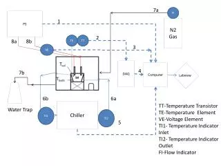
T9-PS Setup discussion. Beam dump (current simulation 40X0 W). PS-T9 setup Brem g 50 MeV few~GeV e - , p , p 1-15GeV. NaI CAL. S3. Si4. Si3. CU. magnet. T2. S4. T1. S1. Si1. Si2. S2. C1. C2. TRD. C1-C2: Cerenkov counters from CERN (e/ p PID )

E N D
Beam dump (current simulation 40X0 W) PS-T9 setup Brem g 50MeV few~GeV e-, p , p 1-15GeV NaI CAL S3 Si4 Si3 CU magnet T2 S4 T1 S1 Si1 Si2 S2 C1 C2 TRD • C1-C2: Cerenkov counters from CERN (e/p PID ) • S1-S2-S3-S4 (maybe not all): trigger/veto scintillators • TRD (for calibration at PS, required at SPS, e/p PID): 16 modules with radiator and double straw tubes • Si-n: silicon detectors with 384 strips for g-tagger • NaI CAL: g-tagger calibration, not critical, coming in june • T1-T2: Time Of Flight scintillators (protons PID) – we don’t have it yet – who can provide it? Current lever arm is ~8 mt - working with liaison physicist to allow ~20m lever arm Page Number
Optimize PS Tagger experimental setup MWPC • Current setup working in clean room - BASELINE • 4 XY SSD ~9 cm active area from AGILE • Support mechanics with rails allowing various locations • Full AD DAQ from INFN-Bari optmizing readout rate using 0-suppression g-tagger (beam arm) magnet g-tagger (tag arm) Beam dump CU
Optimize PS Tagger setup • Energy limit from available room in T9 • Max ~3 GeV (lever arm) • In principle <100MeV (demonstrated in the past) but hard to define because of coincidence of unradiated beam and low energy gammas • checking on following ideas with liaison physicist • increase length by removing MWPC and 1 cerenkov, move magnet upstream the beam • try fitting the magnet at an angle to increase bending power (can gain factor 1.4 working at 45o) • Intrinsic tagger limitation on resolution • Proposal to use tagger info within limited range • Decrease primary e- beam energy to cover low energy g • Stable beam configurations in steps of 1 GeV • Minimum available e- beam ~500MeV but don’t know rate and was never tested by us • Use CU energy info below that threshold (E-recon, PSF) • Optimize geometry to maximize data flow • Current DAQ test show a maximum readout rate of ~<500evt/spill (800ms deadtime, 400ms spill) • Position Si (location and relative distance) to maximize acceptance and match max data rate (Sandro) • Consider more silicon layer (Bari) • INFN will study setup and propose optimized layout
Optimize PS experimental setup Resolution limit (Philippe from energy recon studies) 2000 1000 Position to match max data rate and ∑ evts in SSD g energy (MeV) extra SSD to extend energy acceptance extra SSD or plastic for beam monitor 1 SSD ~9 cm width (currently the only available) 1200 600 400 200 g trigger plastic e- beam 2.5GeV BT=0.5 e- beam 1GeV BT=0.25 e- beam 2GeV BT=0.4 Transverse distance of e- in tagging arm (mm) (g energy derived by difference with Ebeam) my visual attempt to summarize discussions from the workshop BT/Ebeam = const. to keep geometry